
Hi all,
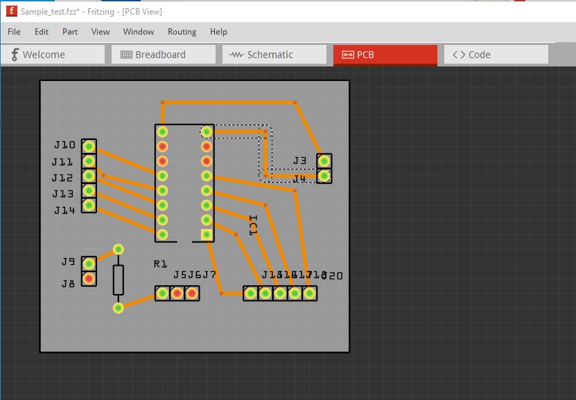
The red circles in the bottom left and top right are the ground pins in my circuit how do I make it ground in the PCB? I looked at ground fill and ground seeds but am a little confused about that. Any help is appreciated.
It would probably be a better bet to upload the .fzz file of your sketch (upload is the 7th icon from the left in the reply menu.) Images are pretty much useless usually when trying to answer a question. In this case it is unclear where ground should be. Presumably your schematic indicates where ground should be?
Peter
1 Like
Sample_test.fzz (9.8 KB)
the 4 pins j9,j8, j3, and j4 are the pins for my power supply, one is the Vcc while the other is the ground. How do I make the ground pins by adding copper fill and can I connect the j7 pin ( grounding for my temp sensor) and any other pins I might need to ground to those as well?
Well in this case the sketch isn’t making things much clearer. J3 is connected to the common of the IC, Assuming J3 is the positive of the power supply that would be correct. j4 is connected to nothing currently, assuming that is the ground connection it should be connected to ground like this:
I expect although that is not at all clear. Presumably j8 should connect somewhere as well but it isn’t clear where as it isn’t clear what j8 is.
Peter
1 Like
J8 is the ground for my 5v power supply while J4 is supposed to be the ground for my 12V supply. J7 is the ground for my temperature sensor. My question is can I ground that to an external ground or is there a way to add grounding onto the PCB itself? Yea sorry about the schematic I started on the breadboard and jumped to the PCB.
Then this should do what you want so long as the external 5V and 12V grounds are separate. You want to avoid a ground loop (two paths to the same point) so the grounds need to be separate outside the board.
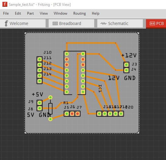
at some point (preferably internal to the board to avoid logic level problems due to voltage drop in ground between the 5V and 12V grounds) the grounds need to be common, but only in one place to avoid a ground loop. You shouldn’t need a ground fill as the current draw here shouldn’t be that high.
Peter
1 Like
Ahhh makes sense just for my understanding though, could you please explain to me about the ground seeds and fill?
Also in the picture you have provided all the grounds are connected to each other can I then connect one of these ground points to an external one like in a breadboard circuit?
Ground fill (and the seeds) floods blank areas of the board with copper. It is usually used for ground planes in analog circuits or in high power applications with large current draws. I’m not all that familiar with ground fill (I rarely use it) but I think the seeds are to indicate that an isolated area should also be ground filled.
You can but it can cause problems. If you are driving 1/2 amp from one of the outputs that can cause a voltage drop in the ground which in turn erodes the noise immunity (which is only about 0.6v) on the logic inputs. It is a better bet to have the logic ground (the 5V ground in this case) separate from the high current (12V ground) as it is in my image. The 5V ground connects directly to the ground on the IC, and a drop due to high current in the output circuit won’t affect noise immunity in the logic circuit.
Peter
1 Like