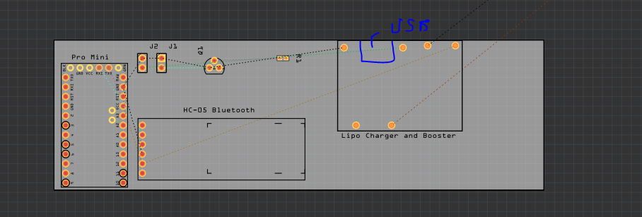
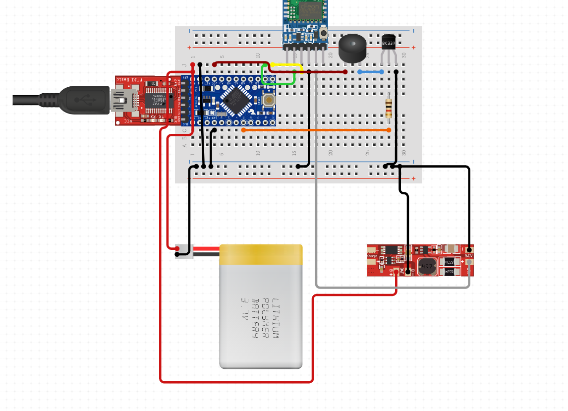
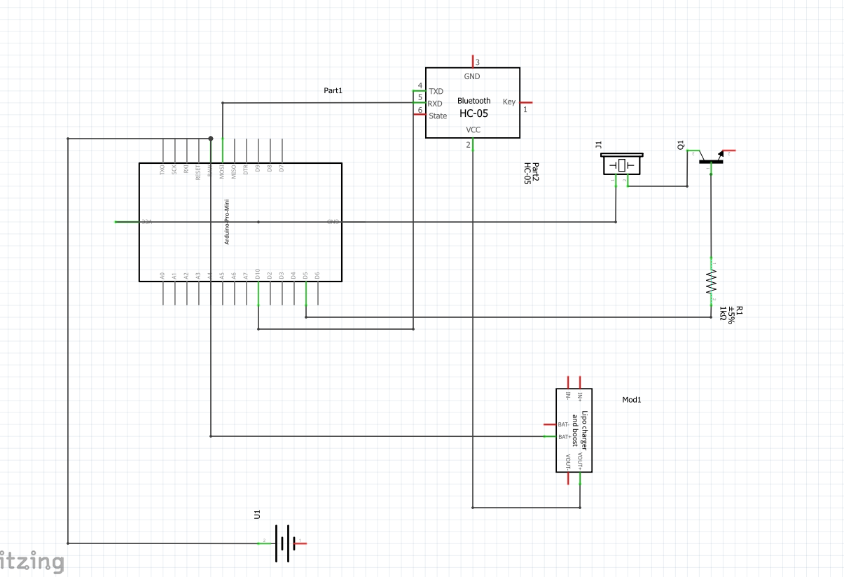
Sorry pretty basic question here, I am trying to convert a breadboard to a schematic but the breadboard has a ground rail which I am not sure where it would go on the schematic. If I draw it on the breadboard part of Fritzing it doesnt show up on the schematic as it is from a microcontroller, (potential glitch or i’m not good at this?) Breadboard:
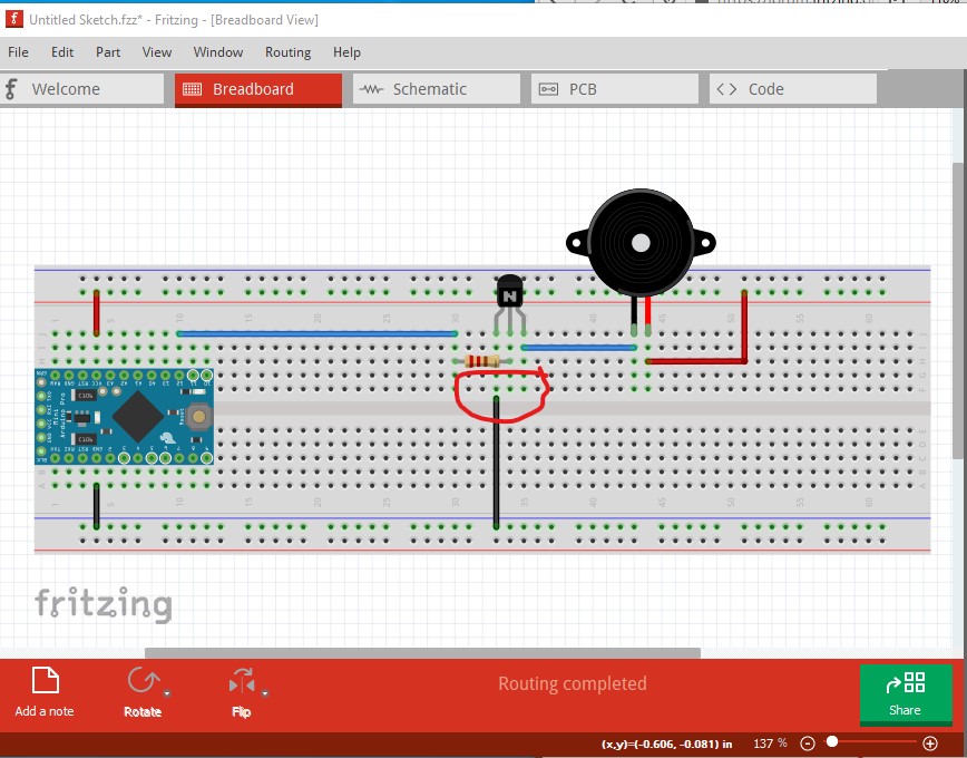
The most likely answer is that you don’t have a connection in breadboard (the pins should be green, not red which indicates no connection.) Here I made part of your circuit with an intentional error (the ground wire to the transistor is not connected, circled in red here.)
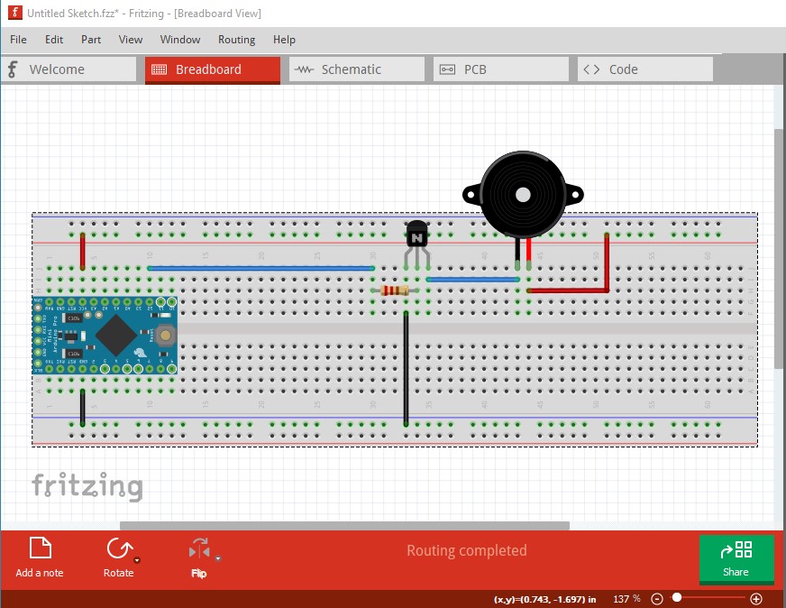
which now shows the connection to ground. An alternate way to find this is to left click click on a pin on ground. Everything that is connected (which in this case does not include the transistor!) lights up yellow.
Note the end of the wire shows yellow but the row of pins to the emitter of the transistor does not, as it isn’t connected. As well it is usually best to upload the sketch (the .fzz file) that doesn’t work as then we can load it in to Fritzing so see what is wrong.
Ok, I have gone through and ensured all ground wires have connected to holes, and some schematic wires have. However, the wires that are blue in my project are not showing up as dotted lines in the Arduino.
Project: Untitled Sketch 2.fzz (34.1 KB)
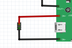
Another question I have for you @vanepp is about the Lipo charger and boost you made, what do I need to connect the IN+ and IN- to in my project, as they seem blank.
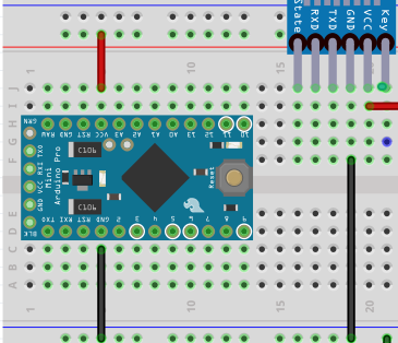
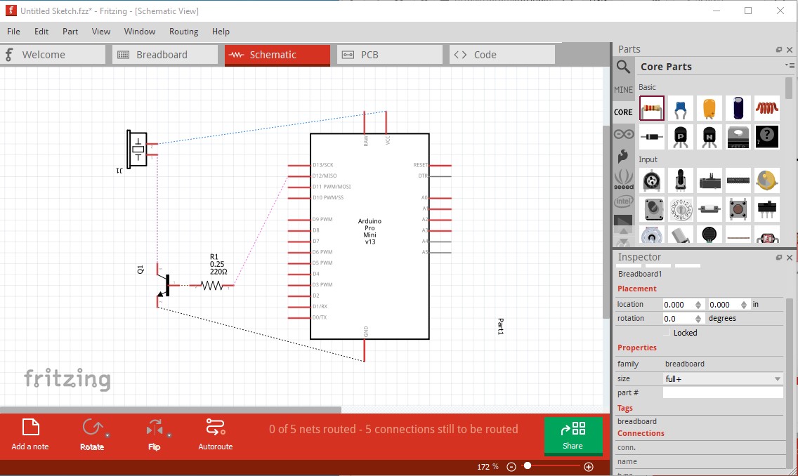
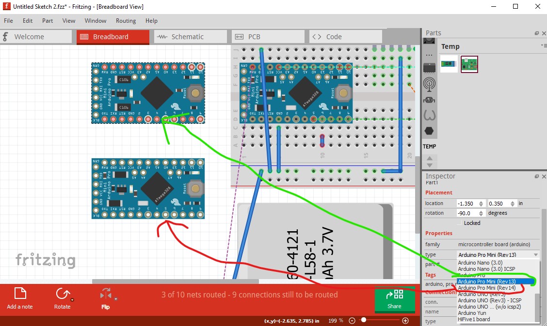
Learned something new! We have two versions of the pro mini, and you have the wrong one for breadboard use. Your sketch is using rev14 which has female pins (and female pins don’t connect to the breadboard) so you would need to connect wires directly to the pads on the pro mini. A better bet is to use rev13 (which is what I used in the sketch above that worked) which connects correctly to the breadboard.
you can change between the two versions in the type field in Inspector. As you see by the red pins (except for the ICSP pins on the left end which are intentionally female so they don’t short on the breadboard) the pads are all red (indicating not connected and male) in rev13. Rev14 below it has no red pins (as they are all female) and thus don’t connect to the breadboard only to wires (which will connect to either male or female pins) Nasty effect for someone new to Fritzing, but I guess someone needed an all female pin pro mini for something. As an aside, you should likely only connect one of the ground wires on the pro mini. AFAIK they are shorted internally and the second ground wire will cause a ground loop which is undesirable.
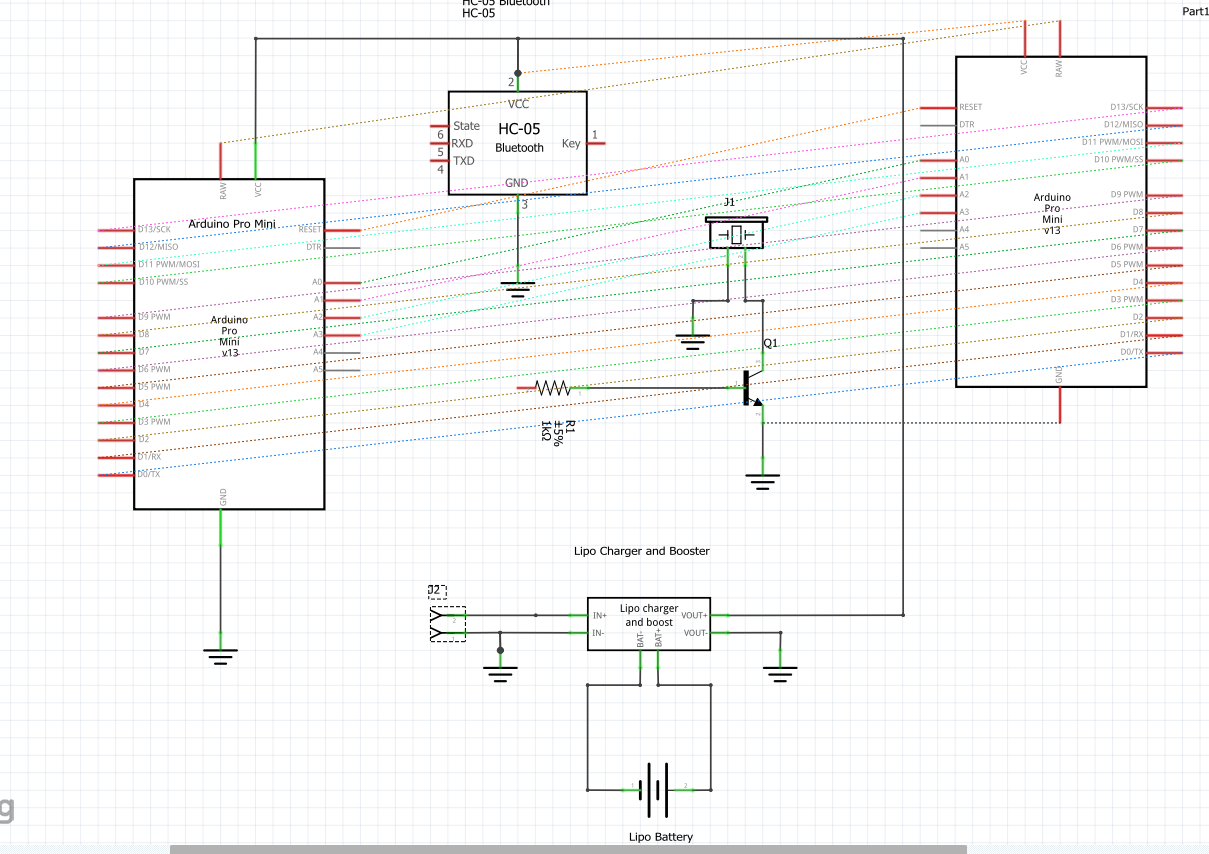
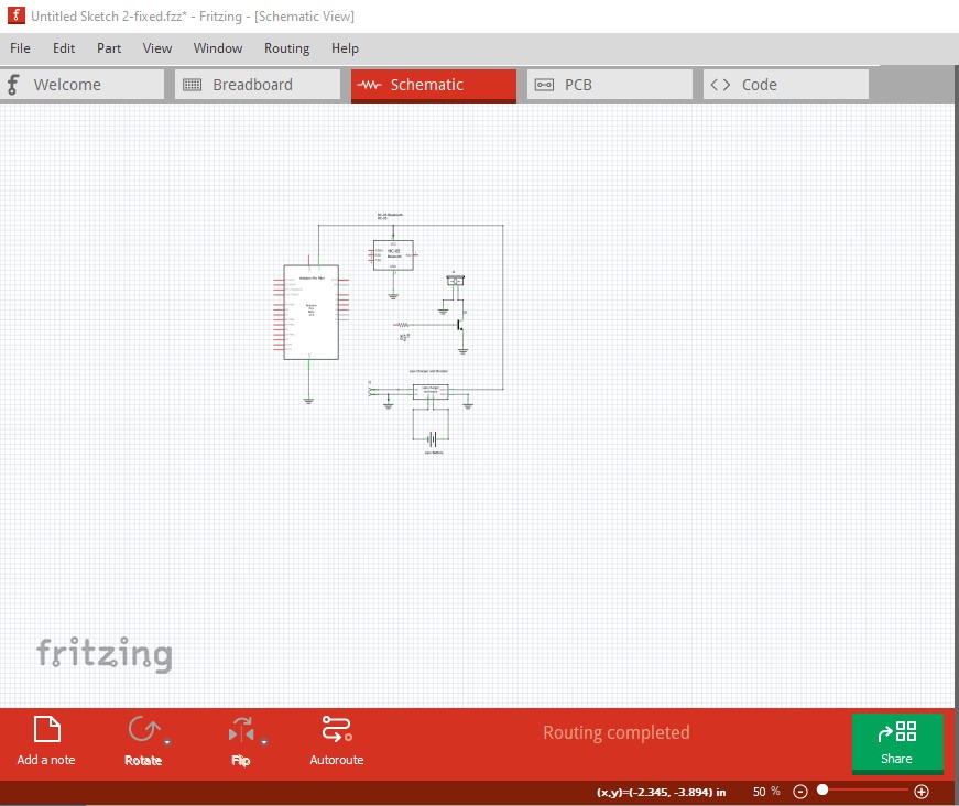
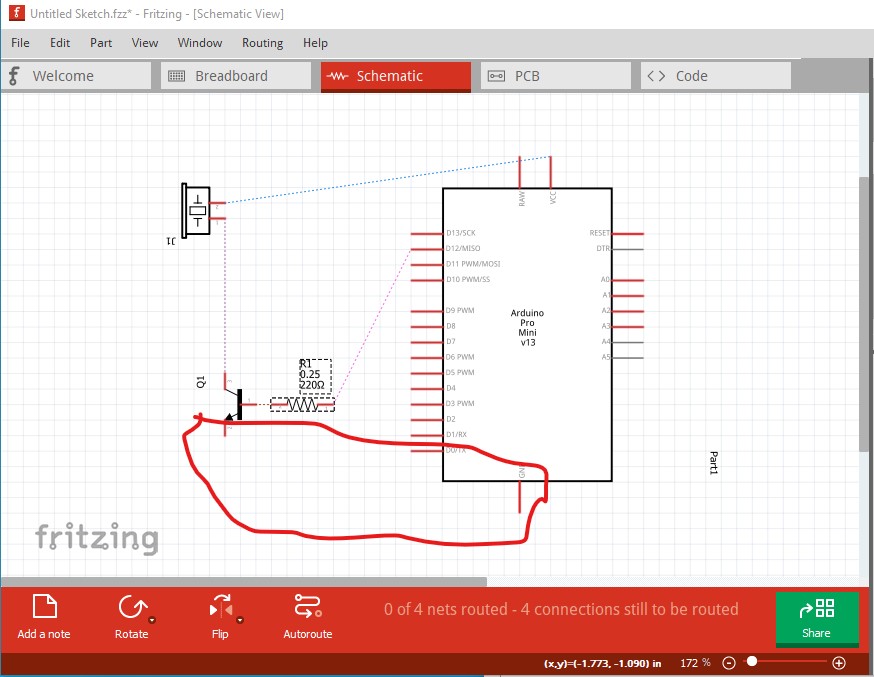
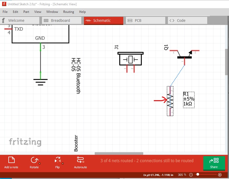
The -In is ground (I expect it shorts internally to all the other - pins but I don’t have a board to verify that!) The +in pin wants to connect to a source of 5V to 7V power to charge the battery, so to a wall wart or USB connector that will provide power. As well the pro mini should be connected to Vout+ from the boost supply not the battery as shown. In addition it looks like you have hit a Fritzing bug (that we haven’t been able to reproduce yet) where, when you make change in more than one view in some particular sequence that I haven’t found yet, the routing database gets corrupted. In this case the indication is this rats nest line that shorts the resistor:
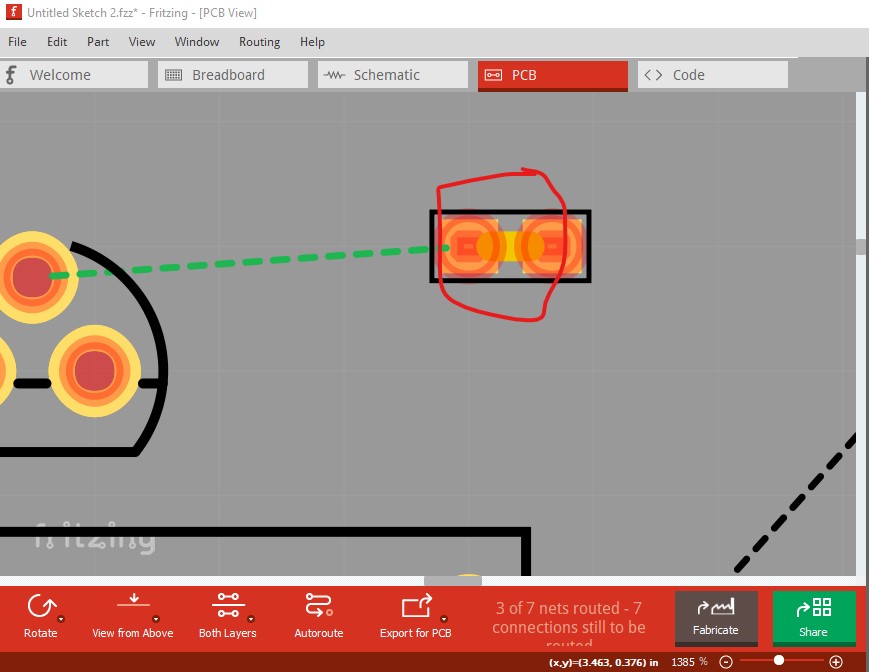
there are no connections in any of breadboard, schematic or pcb that should cause that rats nest line. The only solution I know of is to delete all traces in all views and run the wires again. The usual advise to avoid this is to wire the circuit entirely in one view (usually breadboard or schematic, but pcb will work) and then click on and route the rats nest lines in the other two views to make the connections. Turns out I’m wrong, in pcb there is a short across the resistor:
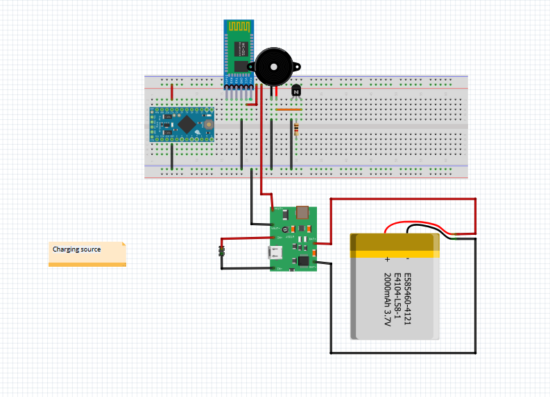
and removing that fixes the issue. Here is a new copy of your sketch with my corrections. The boost connection drives both the HC05 and the pro mini with 5V from the boost supply (making it independent of the battery voltage.) A two pin header (which could be a barrel connector if you are using a wall wart for charging power) indicates the connection to the charging source.
Sorry @vanepp I’m just wondering, will this circuit do exactly what my original schematic will do or do I need to change any wires (Might be a dumb question).
Also, You were talking about connecting a USB head to the charger/booster to the IN+ and IN- ports. Is the one pictured below “artificial” or would it automatically connect if I bought one.
Finally, the schematic shows 2 Arduinos whereas the project only has one which is a bit confusing.
The only dumb question is the one you don’t ask ,
that said, no it isn’t identical to your original circuit, but that circuit likely won’t work. The raw pin has a 5v regulator connected to it, so the input voltage needs to be something like 7V or so (to a max of 12V I think.) A single cell Lipo battery is 3.7 to 4.2V (discharged to fully charged) so doesn’t have enough voltage to support the regulator on the raw pin. That is why you need the boost regulator on the charger board. Connecting the +Vout pin from the boost supply to raw on the pro mini, and adjusting the boost to be 7V will work, and then the HC05 will connect to VCC on the pro mini (which provides regulated 5V from the regulator on the pro mini.) As will setting the boost voltage to 5V and applying it to the VCC pin and the VCC of the HC05 (which is what I did here.) Your original circuit is also lacking any charging supply connection, you would need to supply a power source to the two right side pins of the boost module to charge the battery. Note that the new boost module has a micro USB port and if you connect a USB cable to that, then the USB port will provide the required charging power, as an alternative to the Vin pins (I wouldn’t use both, the boost module would hopefully protect the USB port, but may not in which case you may damage the USB port if the Vin voltage is higher than 5V.)
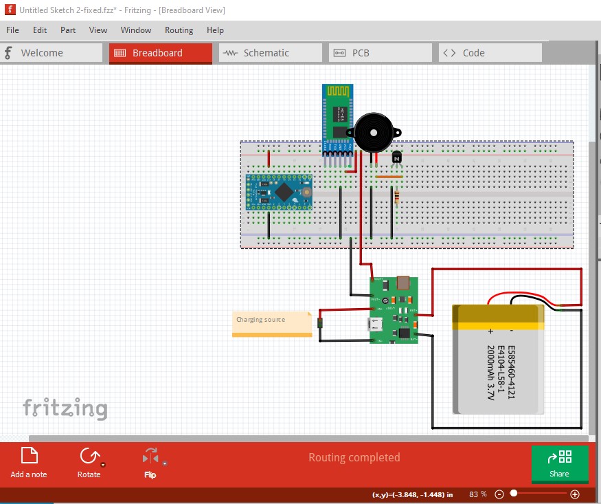
My original .fzz has only one, there is however an oddness (which seems to be a Fritzing bug perhaps) in that the pro mini doesn’t show in breadboard
The pro mini is actually there and will show up if you right click on the breadboard then click Raise and Lower->Send to back. This is a bug because breadboards are supposed to always be the lowest layer and not appear above anything else or at least so I was told when I started in Fritzing 5 years ago.) After clicking Move to back the pro mini re appears in breadboard
I would guess that you thought I had forgotten the pro mini and dragged one in which will indeed create two (on top of each other.) Deleting one of them should fix this up.
On the circuit you made for me @vanepp, do I need to connect RX and TX or do I do that on the PCB?
Also, about the HC-05, if I have in my code on Fritzing to connect to my phone, I’m guessing the program is not capable of doing this?
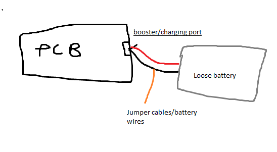
And finally for the PCB view, am I able to have the battery off the board or does it need to be routed through copper?
You should connect RX and TX in breadboard then it will reflect the connections in to both schematic and pcb.
While I don’t know a lot about bluetooth, as long as there is code available for the Arduino to interact with a phone that should work.
You would need something like a 2pin header on the pcb to be the connection to the battery, but the battery itself can be off board connecting via wires to the two pin header (you may want a polarized connector to prevent connecting the battery bacwards!)
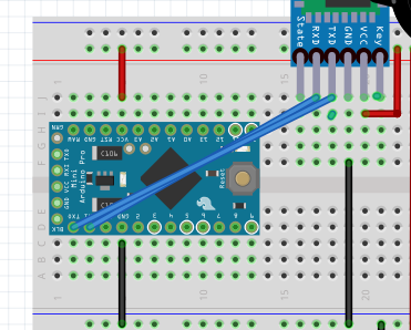
Do you know if its a simple RXD to arduino RXD and TXD to TXD or something else (blue wires)
You would need something like a 2pin header on the pcb to be the connection to the battery, but the battery itself can be off board connecting via wires to the two pin header (you may want a polarized connector to prevent connecting the battery bacwards!)
Still a bit confused at this, my current setup is below with the USB connector at the edge to allow for easy access to the hole. Where would I locate the 2pin header on Fritzing and where would it go on the PCB (I’m guessing next the the charger so connects to the Battery)
Other way around. RXD on the HC05 to TX on the Pro mini and TXD on the HC05 toRX on the Pro mini.
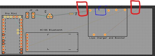
Yes, something like the Sparkfun prt 08233 (search for prt 08233 in the parts search and it will come up) the has a connector that will only connect one way so you can’t connect the battery backwards would be the best bet. Put it beside the Charger as it will also need a hole in the case for the connector from the battery to connect to. Either of the positions marked in red will do or where ever is best from a case point of view.


 I was wondering why it was only possible to connect the Arduino instead of breadboard.