Work arounds and alternate processes.
I have seen similar glitches using Fritzing before. Here are some ways I have found to reduce the likelihood of problems. The greater the number of ‘nodes’ in a net list connection, the more likely there will be problems. Sometimes splitting wires into multiple groups, that join at pins (instead of in the middle of wires) works better. That is not always good either, because is usually means wires directly on top of each other, which causes different problems when parts are moves.
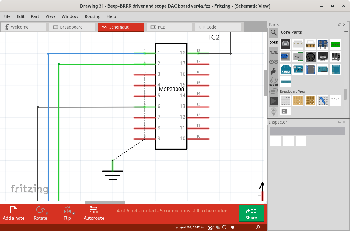
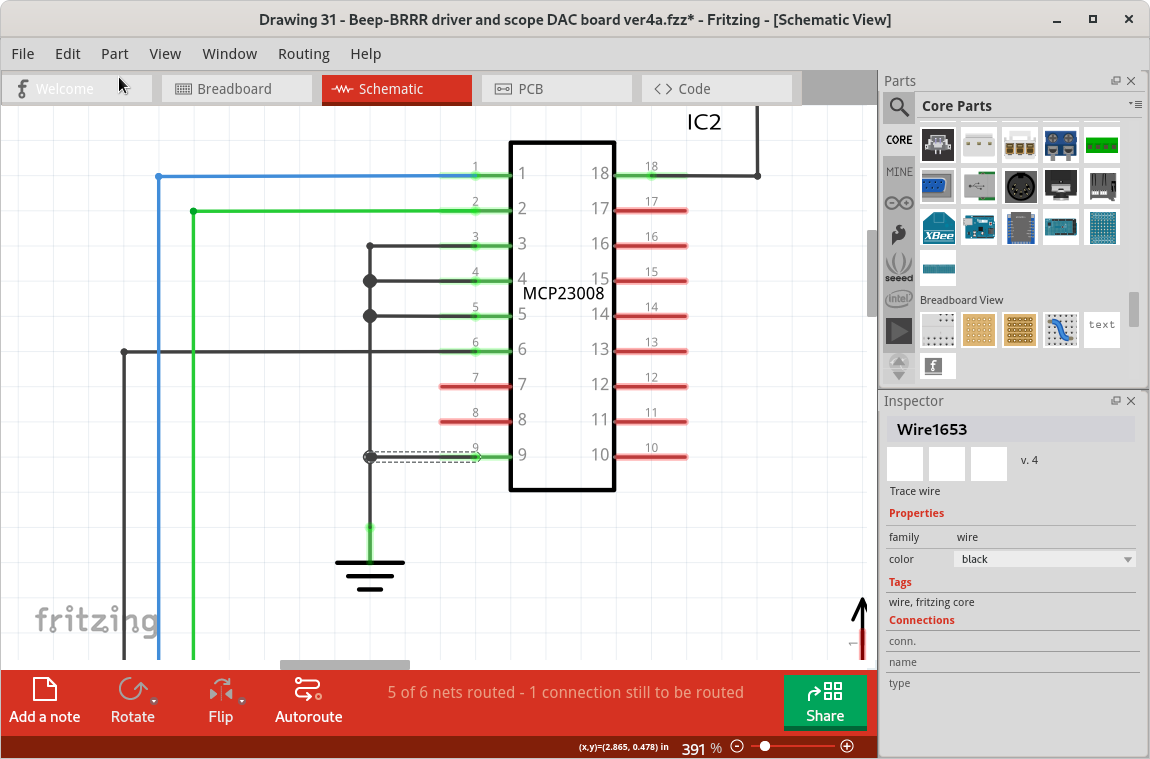
For a net list with a large number of in wire nodes (join points), I have found that creating the longest wire first, then creating ‘taps’ off of it works best. Create the wirem (approximately) route it where you want, create bend points where you want the wires to join, then add wires from pins to the bend points. Finally, move the bend points and finish the routing. For the example below, I started by connecting a wire from pin 3 of the MCP23008 (IC2.3) to J9.1. I routed that (dragged out bend points) wire approximately in position, then added extra bend points (drag into a zig-zag) beside the other pins to be connected. Where the initial routing had not already created a bend point. Dragged wires from each of the remaining pins to the bend points, then cleaned up the routing. No glitches seen.
Drawing 31 - Beep-BRRR driver and scope DAC board ver3a.fzz (10.7 KB)
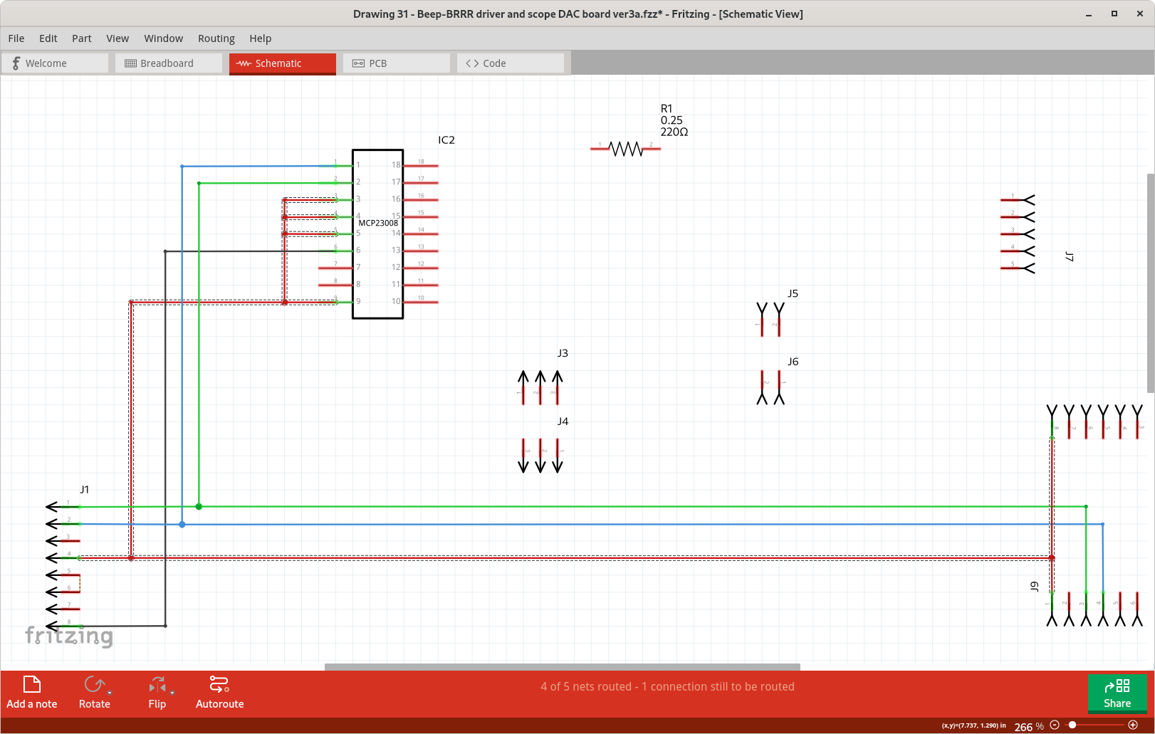
Some of the largest net lists can be simplified graphically. The one that you had problems with is actually the ground net. Schematics use a specific symbol for ground, that can be duplicated all over the drawing. All ‘grounds’ are connected together without needing actual ‘wires’ on the drawing. There is another symbol used for power distribution. Fritzing also has a ‘net label’ that can be used to create custom ‘bus’ nets, which can simplify the drawings a lot when there are a lot of nodes in a few nets.
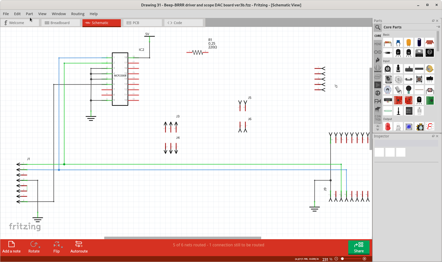
Detailed steps for creating a ‘long first’ net for the gnd connections on IC1