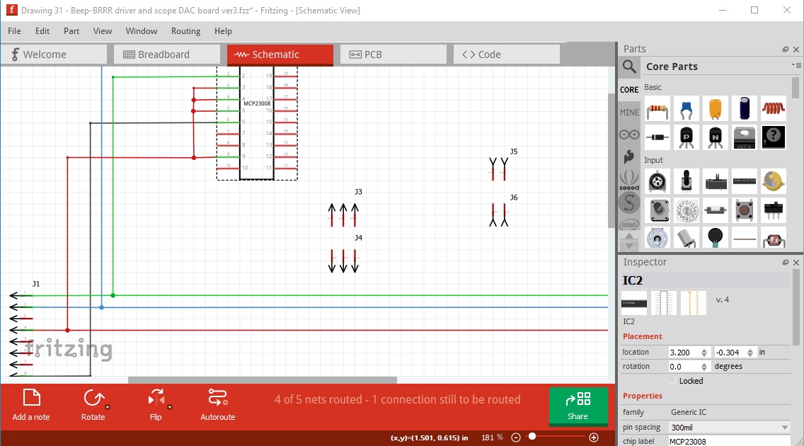
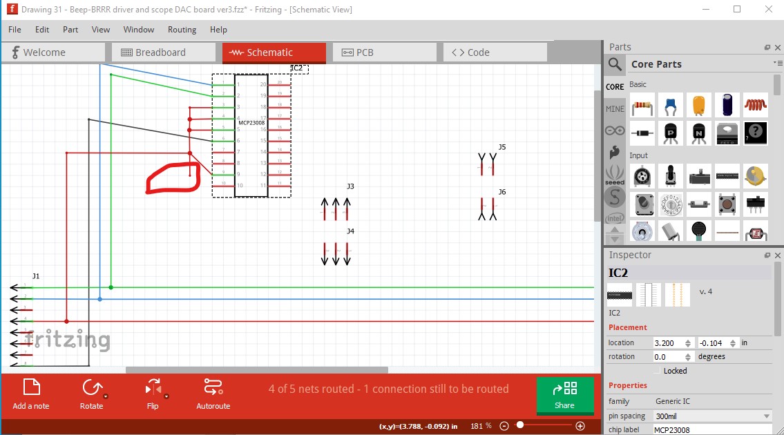
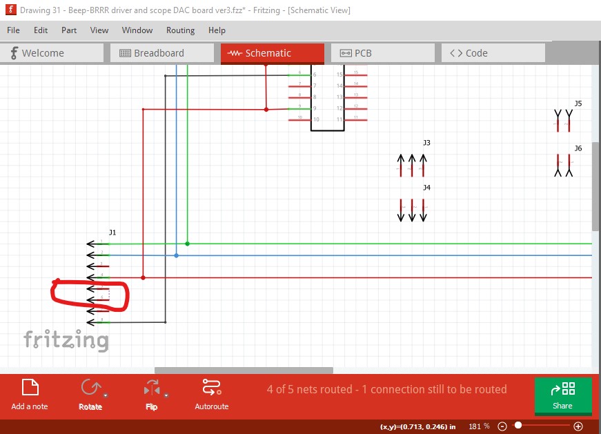
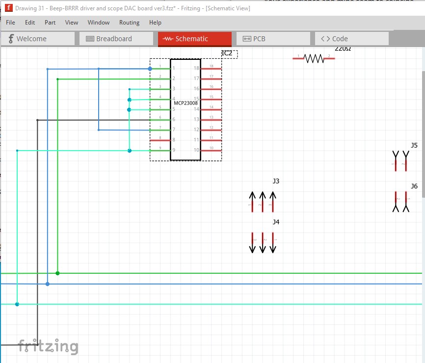
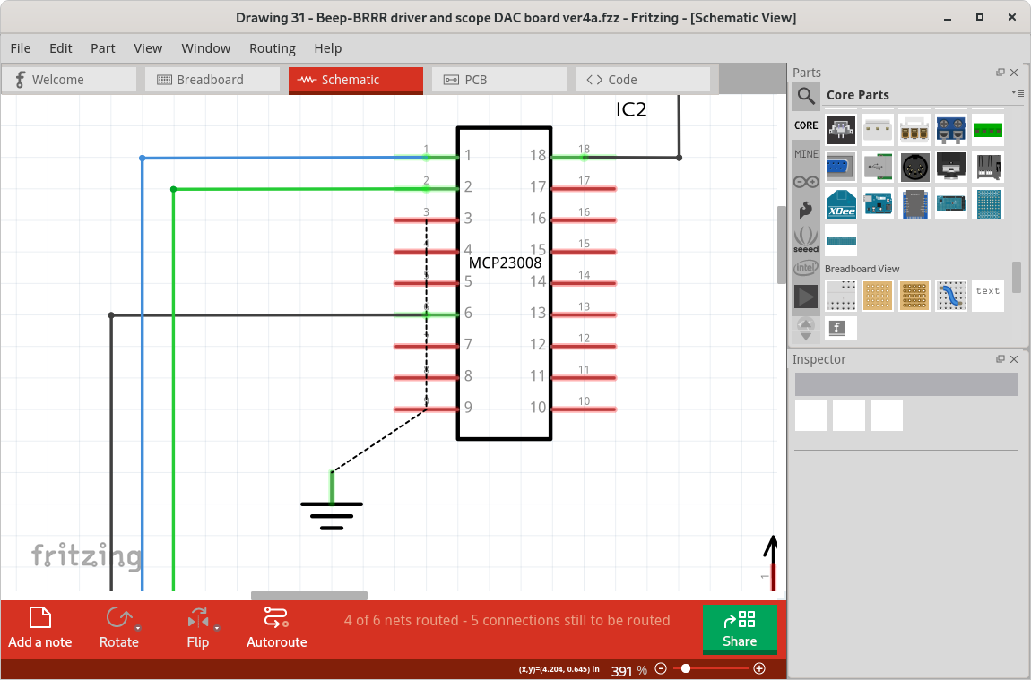
During my first ever schematic I seem to have been able to make a circuit of the red wires. If I change colour, all of the subwires change color. However, if I push the IC up or down, there is one connection that does not follow (see screen shots).
Is this correct? Probably not, so what might I have done wrong? I’m on macOS, and looking at some Windows-based YouTube videos didn’t help me. And I didn’t find any “official” videos on Schematic view at all. But I’m sure there must be one?
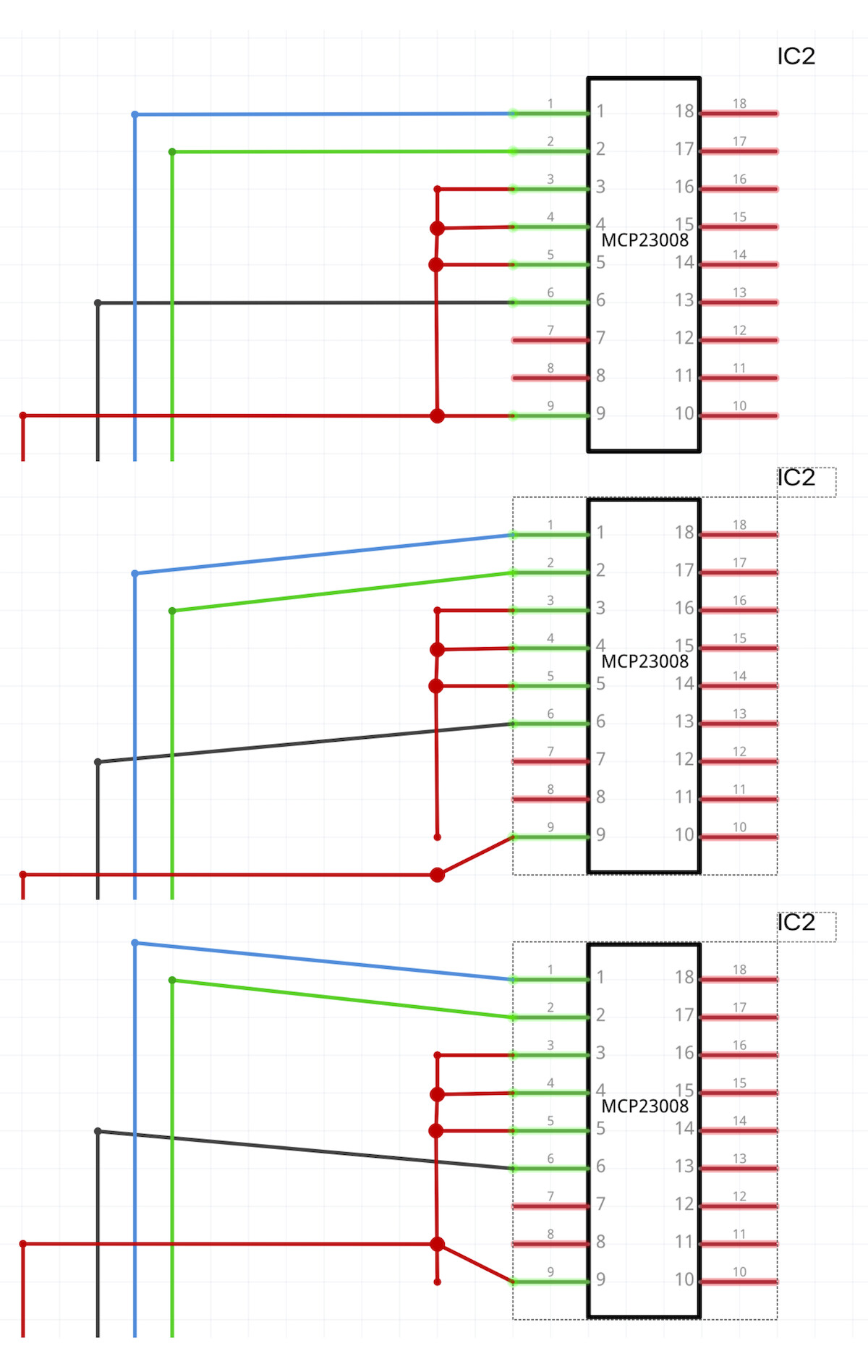
Upload the sketch (the .fzz file, upload is 7th icon from the left in the reply menu) and one of us will have a look at it. If you left click on any pin, all the pins connected to it will light up yellow. That should indicate that pins 3,4 and 5 don’t connect to pin 9.
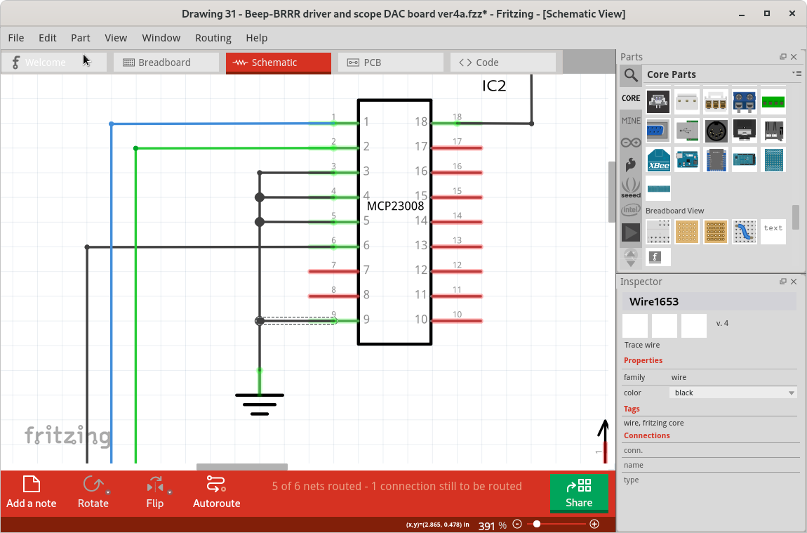
The likely answer is just that the ‘open’ end of the wire did not get connected to the join point in the other wire (or got disconnected later). Should be able to fix by just dragging that open end point to the join (big dot) in the other wire.
To avoid needing to do extra cleanup later, move the part like in your example, to where you can see the open end, move the open end somewhere else, where the end will still be visible when the part and other wires are in the original location. Move the part back where it started, then move the open end point to the bigger dot. Once that snaps into place, you should only have to (maybe) drag the dot a little to get it to snap back to the grid.
I had tried both of those methods (if I understand them correctly). It looked like they connected, and they were (changing colour or left lclicking), but went loose when I tried the initial exercise again.
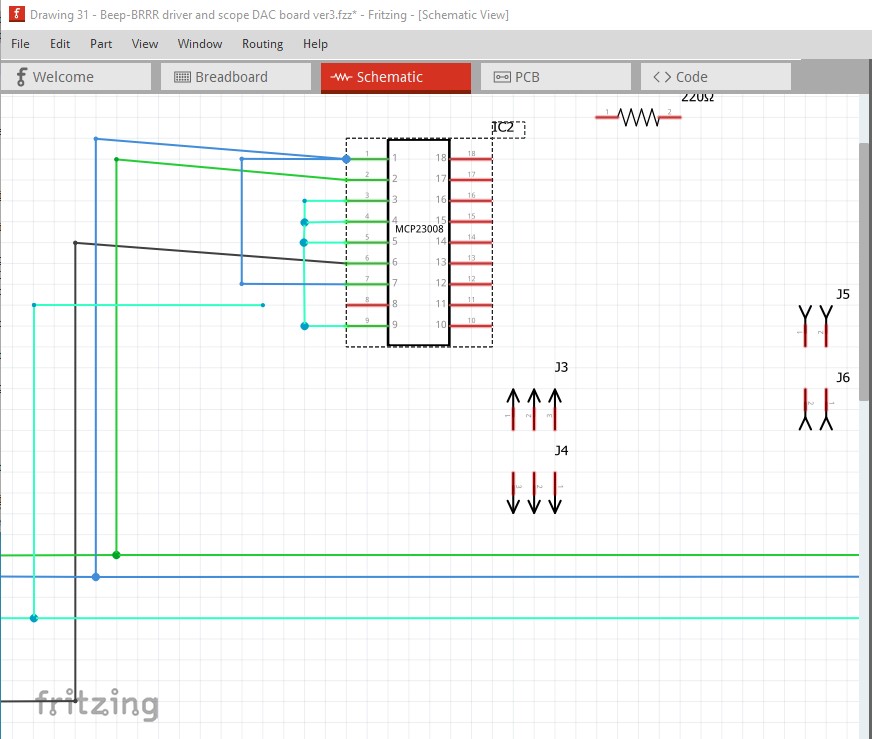
it should have shortened to stop at the wire to pin 9. Going the other way (moving the generic IC up) causes the problem you see, again the line does not rubber band to maintain the connection.
The routing database appears correct as it thinks all the pins are connected. What Fritzing version are you using? This is 0.9.9 on Windows 10. I see that there are wires connected in PCB (and that there is one unrouted wire)
Version 0.9.9 (bCD-348-0-f0af53a9 2021-09-22) Cocoa [Qt 5.15.2]
macOS Mojave 10.14.6
Typical for a starter. Just messing around.
Take this with a pinch of salt: I have a feeling that this is not a new error. I did test fritzing in 2017 and 2019 and both times I think I gave it up because of this. One file left from that time did not now have this error appear, though.
As @vanepp said, it looks like a bug. The net list is correct, but the rendered wire is not working quite right. As a simple demo, with the disconnect visible, click and drag either the open end of the wire, or the dot where it is supposed to connect. All of the ends ‘jump’ together, and the new rendering looks like it is supposed. Until the part is moved again.
@vanepp Separate note: That MCP23008 part has a glitch. The connection points are missing (or have incorrect) terminal IDs. That appears to have been created from a generic IC, and I confirm the same symptom with a new IC part. The problem would seem to be in the factory code. If that one was not already on your list.
Yep. There are a number of problems there. Complicating it is that there is already Fritzing version related correction in the code which makes fixing it even harder …
Interesting to read your comments. I like this response! Good community, where even the proper coders seem to be participating!
With the version I sent you I had indeed tried to delete parts of the net list (yeah!) and tried to join again. Several times. But every time I, to my surprise, got this same result. I didn’t redo the whole net list though.
I guess, in the light that one earlier fix seems to make this fix harder, don’t fix the fix, but go back to an earlier square. (Advice from a 40+ years in the trade, retired now.) If it’s C++ / Qt and it’s a large system - this may probably both be of help, or worse than good - maybe even the reason.
Will I know when a certain problem has been fixed?
In this case, probably not practical either. The Frtizing code has evolved over time, and some of the changes were not totally forward compatible. The code contains sections that follow different code paths based on the the Fritzing version number stored in the part file. Which means that a ‘bug’ fix needs to be included in each path. That is the “Fritzing version related correction”
I have seen similar glitches using Fritzing before. Here are some ways I have found to reduce the likelihood of problems. The greater the number of ‘nodes’ in a net list connection, the more likely there will be problems. Sometimes splitting wires into multiple groups, that join at pins (instead of in the middle of wires) works better. That is not always good either, because is usually means wires directly on top of each other, which causes different problems when parts are moves.
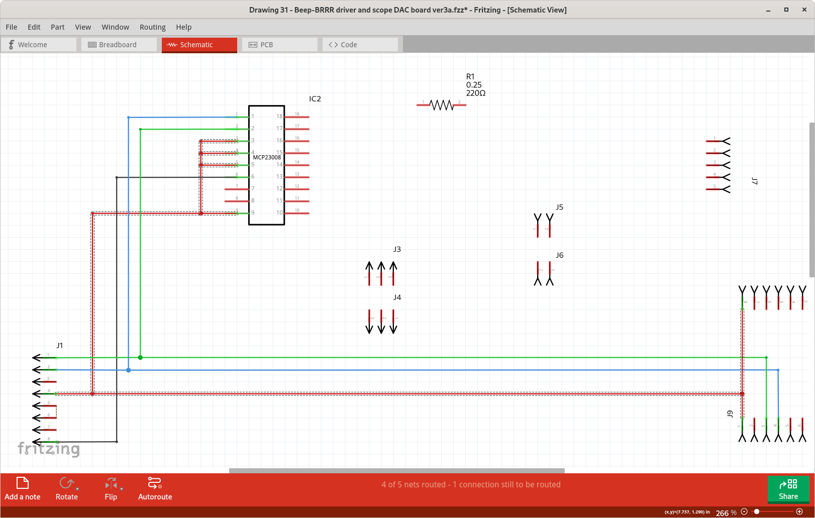
For a net list with a large number of in wire nodes (join points), I have found that creating the longest wire first, then creating ‘taps’ off of it works best. Create the wirem (approximately) route it where you want, create bend points where you want the wires to join, then add wires from pins to the bend points. Finally, move the bend points and finish the routing. For the example below, I started by connecting a wire from pin 3 of the MCP23008 (IC2.3) to J9.1. I routed that (dragged out bend points) wire approximately in position, then added extra bend points (drag into a zig-zag) beside the other pins to be connected. Where the initial routing had not already created a bend point. Dragged wires from each of the remaining pins to the bend points, then cleaned up the routing. No glitches seen.
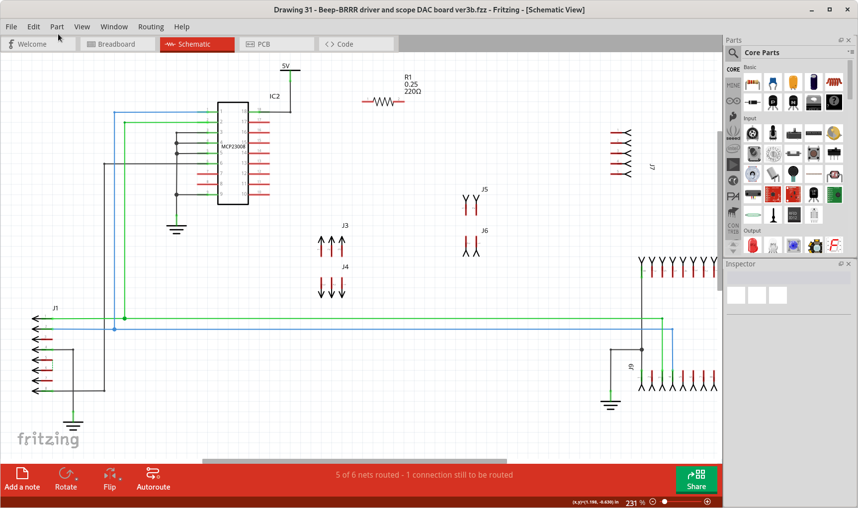
Some of the largest net lists can be simplified graphically. The one that you had problems with is actually the ground net. Schematics use a specific symbol for ground, that can be duplicated all over the drawing. All ‘grounds’ are connected together without needing actual ‘wires’ on the drawing. There is another symbol used for power distribution. Fritzing also has a ‘net label’ that can be used to create custom ‘bus’ nets, which can simplify the drawings a lot when there are a lot of nodes in a few nets.
Honestly spoken. I have worked with embedded systems in Modula, Pascal, occam, C and xC - always with a run-time in SW or microcoded or in HW, with some sort of task/process model. That leaves OO out, usable for its kind - like a CAD system like fritzing I assume.
As much as I appreciate your work with the above, thank you! - I am, sorry to say, less tempted to use fritzing. Arghh, I do like the fritzing concept! (I did start with the longest path.) Unless someone can comfort me and say the risk is low (risk = probability * consequence). In my experience, all of a sudden there is a no point of return continue, and the version control will have to come in handy. But the delta work is lost, and figuring out how to be kind with the tool will be necessary knowledge to survive. 40+ years of some times having to do this (when we bought systems and paid a lot for them and were stuck) is enough. As a retired I have (less years) and higher hopes, even for free SW (but since everybody needs breakfast some € crossing over is fine). I have found an alternative that I’ll try for some days now. I have used iCircuit for years, but it doesn’t do PCB layout.
All tools have a learning curve. Finding the right set of tools for you personal needs is always a challenge. Fritzing is good for hobbyist and teaching, The breadboard view allows showing how an experimental project goes (can go) together. I have enough electronics hardware background, that I normally start with the schematic view. A lot of beginners have trouble understanding the symbolic representation, and the more real world breadboard view is easier for them.
The demonstration was for others as well. Anyone searching the forum for similar problems could find this thread, and get some answers, options, suggestions without duplicating the post and reply sequence.
Fritzing code is a challenge to work with, partly because it was started as a class/university project. It had several different coders, but most would be consider ‘junior’ level at the time. The project explored different techniques as part of the learning, and it shows.
That works. I just tend to like a more visual indication of the intended join point. Plus it is an indicator that the point needs moving for cleanup. Often, when a wire end is dropped on the bend point, the new joint ‘moves’ slightly from the grid point it was on. This way, I know that I need to later align it to the correct grid point. It also quickly highlights the kind glitch seen here. If moving the join point (back) to the correct grid point leaves a wire end behind, it shows that some extra work might be needed to get a clean drawing.