Steps I took that resulted in the problem:
Hi, I’ve been doing electronics for many years now, but just a few months ago I started using Fritzing to make printed PCB’s…I’ve read that Fritzing isn’t the best option for PCB manufacturing, but it’s what I started with and now I like it and I’m use to it…It’s been working great for me until recently that I decided to import my own Logo in .SVG…My .SVG Logo imported just fine after I had to open it with Text Editor and change this: x=“0px” y=“0px” , to this: width=“100%” height=“100%” …But, when I export to Gerber file for production, my Logo on the Silkscreen Top comes out with errors…So, Fritzing isn’t accurately exporting my logo on the PCB…When I export as an Etchable PDF my Logo comes out just fine…I can’t find anything in Fritzing to recognize accuracy when exporting to Gerber…Has anyone here had this same issue or know how to make Gerber files more accurate right out of Fritzing?..What solution do I have for this issue?..Any help would be greatly appreciated, thanks.
…
What I expected should have happened instead:
After successfully printing many PCB’s made with Fritzing, this is the first time I decided to import my logo, which BTW is a simple logo and looked good in etchable PDF… I expected it to come out fine on PCB, but instead of solid image/letters, some letters came out hollow and there were minor details missing…I made a mistake in not checking the files on a Gerber viewer before printing PCB’s because I trusted it would be fine after seeing that it looked good on the etchable PDF files.
…
My version of Fritzing and my operating system:
I’m using the latest version of Fritzing on Mac OS (High Sierra)
…
Please also attach any files that help explaining this problem
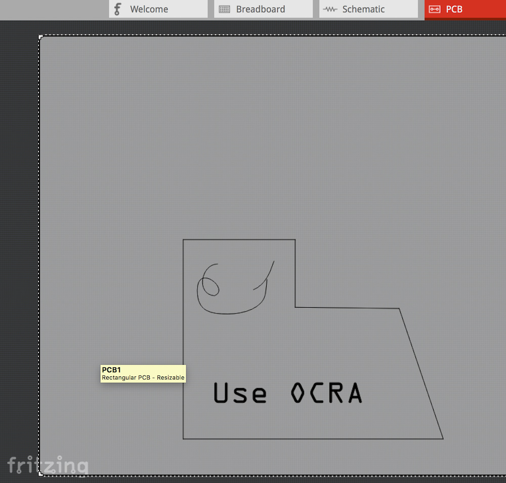
Making a Logo for Silkscreen is simple.
Draw your logo stuff.
Type your logo Text - IMPORTANT: You can use most Fonts but, not all are reliably used in Fritzing.
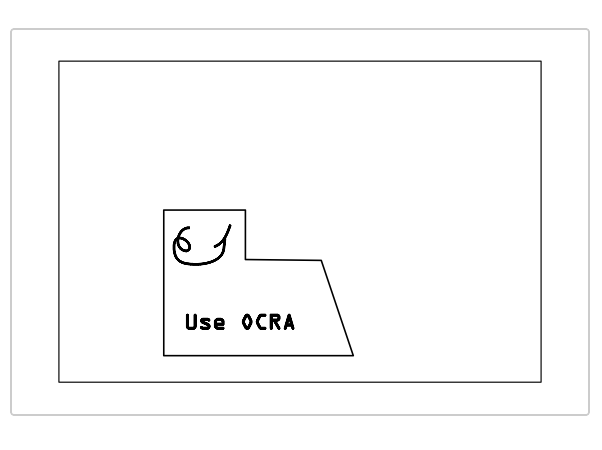
The most reliable fonts are OCRA and DroidSans. (Prefer OCRA).
The “Trick” is to make the text a ‘Path’. Without Pathing the text, sizing and filling leads to problems.
Save it as SVG filetype
[EDIT:
I checked the Silkscreen in PDF but it was empty!
I don’t know why and I never export etchable PDF’s. I export only Gerbers and it works great.
If you intend to use a Transfer method (to get the silk onto the PCB), you can use other software that prints gerbers.
On my Mac (Sierra) I use the Free version of Cuprum
(Change Cuprum background to White and the layer with your silk to black, then print it…)
For using your graphic for only the silkscreen, no layers or other special effort is needed.
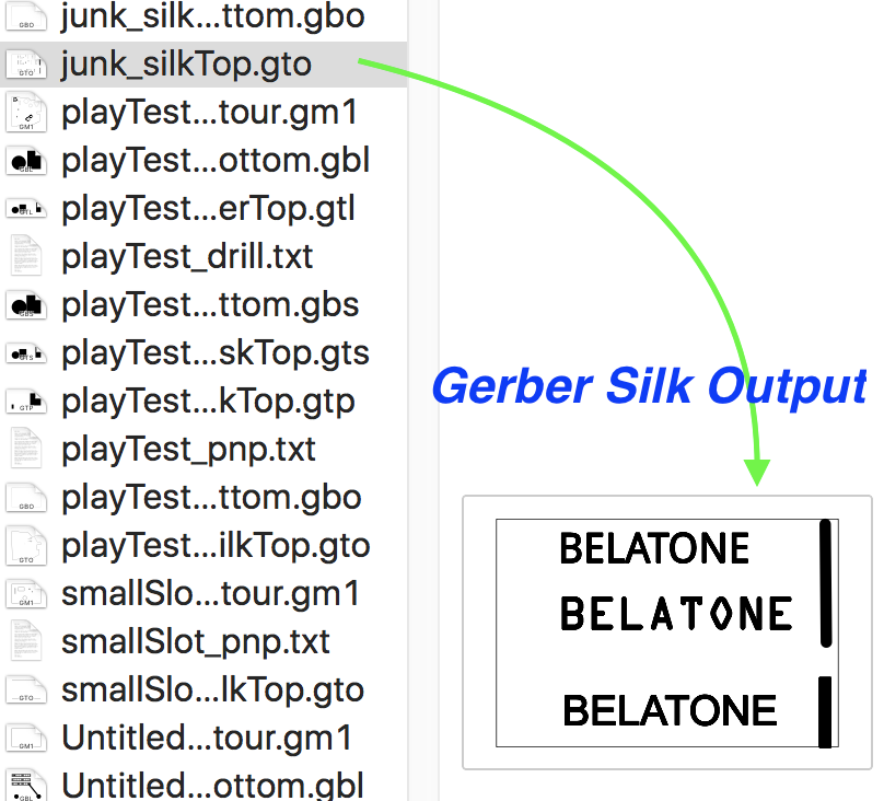
You won’t need them but, attached are Fritzing file with the below example. Screenshots of Fritzing and Gerber file of the silkscreen…
junk.fzz (3.9 KB)
Hi, thanks for the quick reply…I’ve attached the screenshot of what my Logo looks like in Gerber viewer…Basically my image and letters are all solid, but in Gerber they have hollow areas…Does this give you a better idea as to what I should do/try?
Also, I didn’t mention that I’m printing my PCB’s with ALLPCB (China), so I have to send them proper Gerber files without the errors in my logo…You mentioned Cuprum, but can I import Fritzing file and export Gerber file from Cuprum?..So far, my only issue is exporting Gerber from Fritzing, everything exports fine, but my image/logo isn’t accurate…I just downloaded Cuprum and opened my Gerber files that have the logo errors, I can view fine, but what I need is to fix my image/logo with a more accurate Gerber export…
Also, would importing my Image/Logo into Fritzing as a .PNG file instead of .SVG maybe make a difference in my Gerber results?..If so, then what size/dpi does the image PNG file have to be for best results when exporting Gerber?..I ask this because I already tried importing my PNG files with no success, I figured maybe it’s because they’re way too big compared to the file size of my SVG, which imported just fine after editing the file in Text Editor…Let me know your thoughts when you get a chance, thanks again…Cheers!
-
Fritzing was/is not a robustly developed and updated program - thus, it needs user to Fuss and Play around when results are not as desired. Sometimes workarounds produce good/usable results. Sometimes not…
-
Difficult to solve a User’s problem without posting Logo/Graphic/Fritzing file (change the file extension to .fzp so the Graphic file uploads).
Info about graphic software, DPI… etc is useful in solving problems…
-
Fritzing is picky and does not like many fonts.
Try using OCRA and see what happens, Then try DroidSans.
If that works, you know it’s the font used.
Convert the font to a Path.
-
The Graphic should be converted to a ‘Path’. Try Path’ing the entire graphic, try Path’ing individual items… Play around… Ensure Line Strokes are ‘Center’ not ‘Inside’ or ‘Outside’.
-
The Software used can make a significant difference so try other software (and, look for Tip’s and Solutions others have remarked about).
-
SVG or PNG or JPEG or?? Again, try different things, then you’ll know what works or not… (SVG is preferred)
-
Recommend NOT using a Text Editor. But, if using one, be sure to use ‘Plain’ text, Don’t use Rich Text. Ensure UNICODE-UF8 is the export format.
There are other aspects to play with and try - I think others will agree that a solution for one User’s toolchain may not be exactly what’s needed for another User… It took a good bit of work to know what works for the work I do and I still find tweaking is needed…
Regarding Cuprum - I mentioned it only if you needed a Gerber viewer, otherwise ignore.
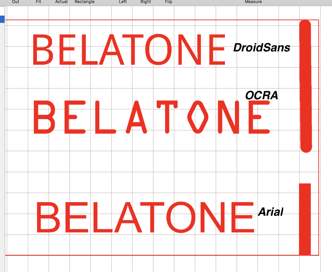
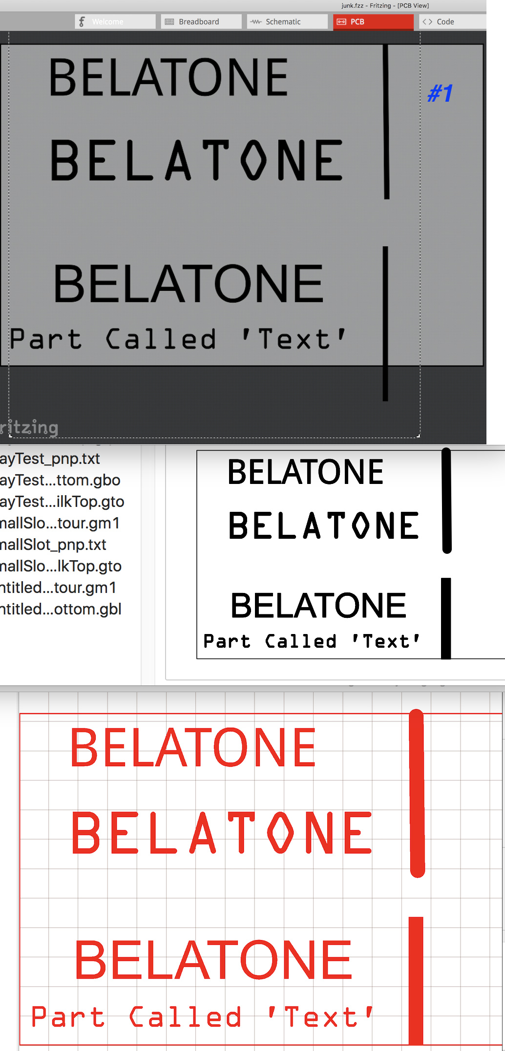
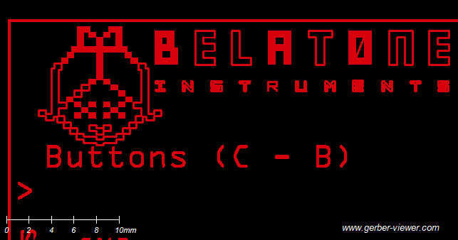
Below screenshot shows “Belatone” with OCRA, DroidSans and Arial fonts. All were 36pt and Pathed and exported as SVG. They look good in the Gerber files (Red is shown in Cuprum, also shown in Mac’s finder window and Fritzing).
You see the Vertical lines are not the correct width as drawn - I did not Play/Fuss with them so, they are as drawn. Hence, you see they are not as intended and show differently in the screenshots thus, underscoring my point about Play&Fuss…
I played around with this to further some points… I did Not fuss with trying to get everything as would be wanted - the goal is to demo the variability and need to Play & Fuss until getting something usable…
Fritzing loads:
-A single Graphic with three Belatone text’s and two lines].
-Added the Part called Text/Logo with Belatone text.
Results:
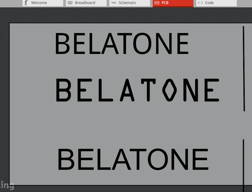
Fritzing shows all is Clear and Cleanly represented (no holes of missing fill areas), HOWEVER, there are differences that bare out when Placing and Resizing the ‘Graphic’; as follows:
#1 The two Lines show in Fritzing with Square Cap ends, as intended by design.
However, The Gerber Silk file shows Mixed Round and Square Cap ends in Mac’s Finder and Cuprum.
Why? Because the Silkscreen Part crossed the PCB’s perimeter.
Notice the Width of the Lines - both are Thick.
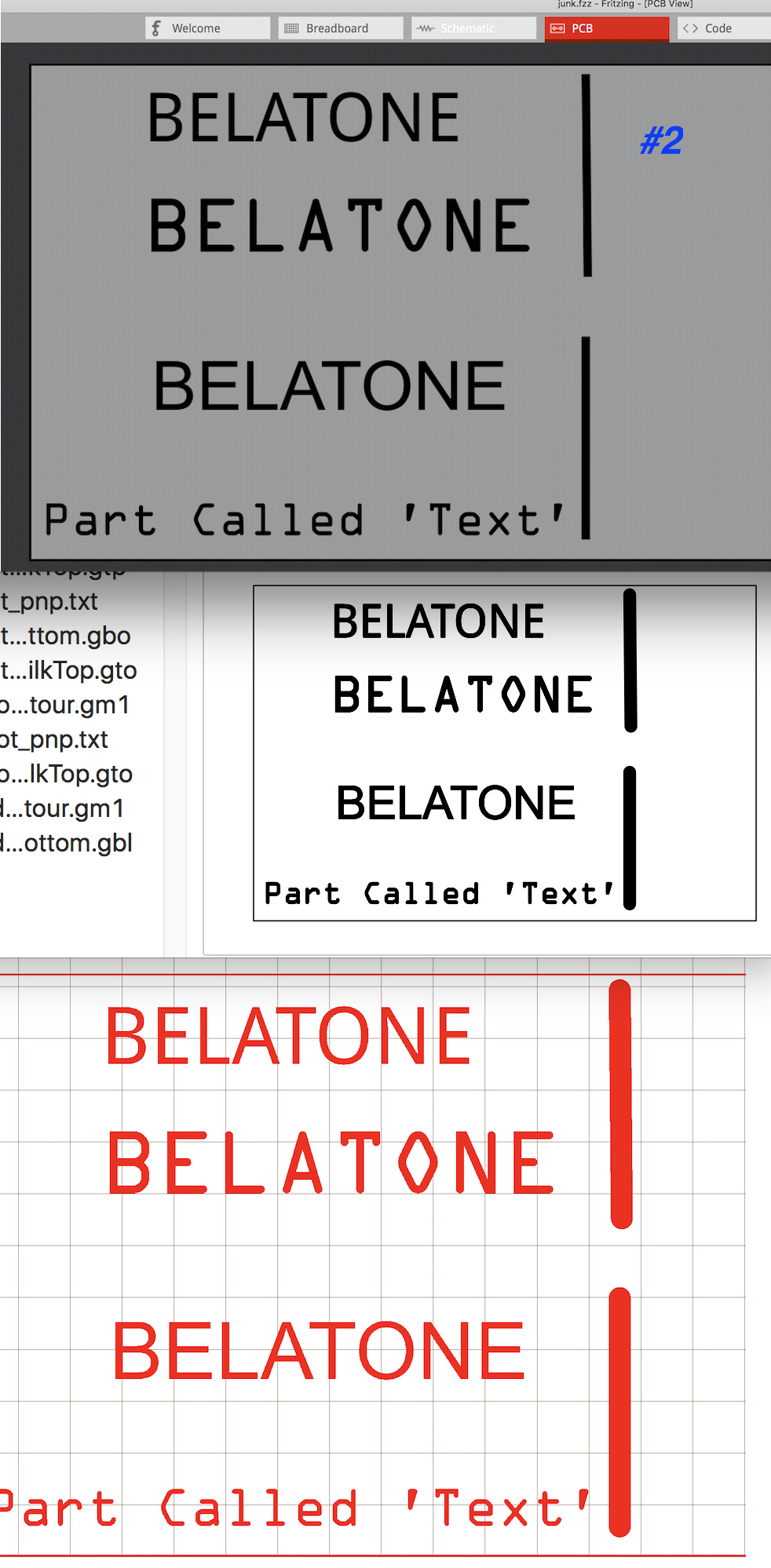
#2 When dragging the Silk Part to reduce it’s size to completely fit within the PCB, the fonts shrink properly but the line Widths don’t shrink.
Fritzing shows the lines as Square Capped, as designed. But, the Gerber shows them as Round Capped.
#3 When dragging the Silk Part to increase it’s size, the lines remain proportional until a certain point, at which the jump to a reduced width.
Video showing the Line Width’s jumping while slightly dragging the Silk part…
Again, the Point of all this is to convey the need to Play&Fuss… So, start with a Simple Graphic, advance to more complex graphic. Repeat with Texts… I did not mention aspects of tweaking the SVG…