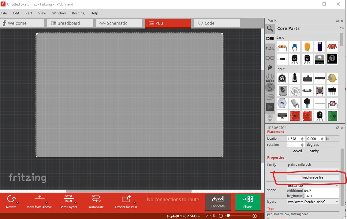
Hello,
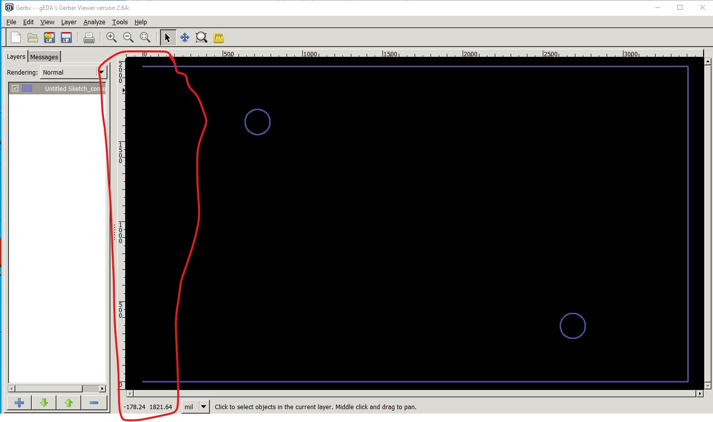
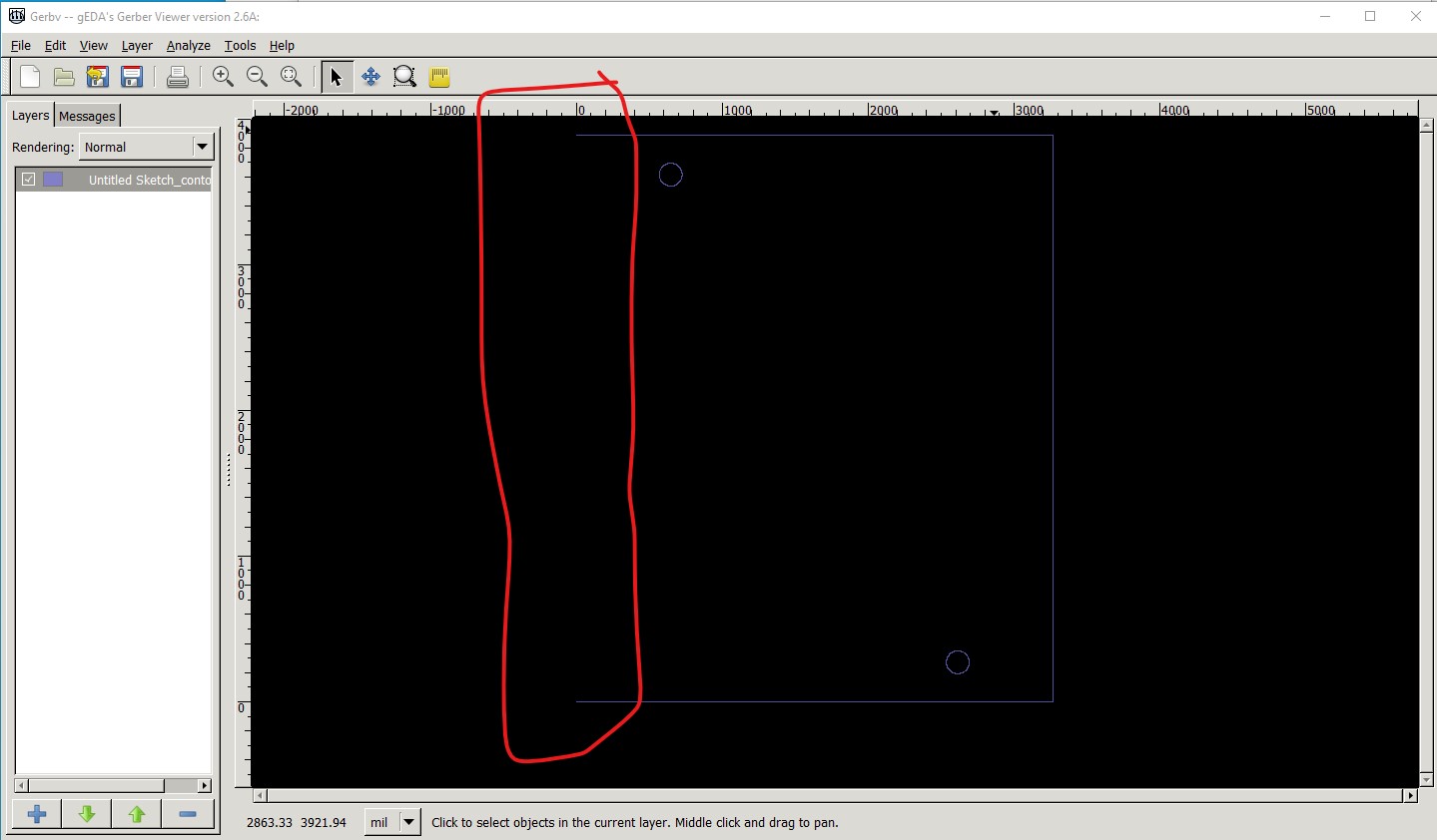
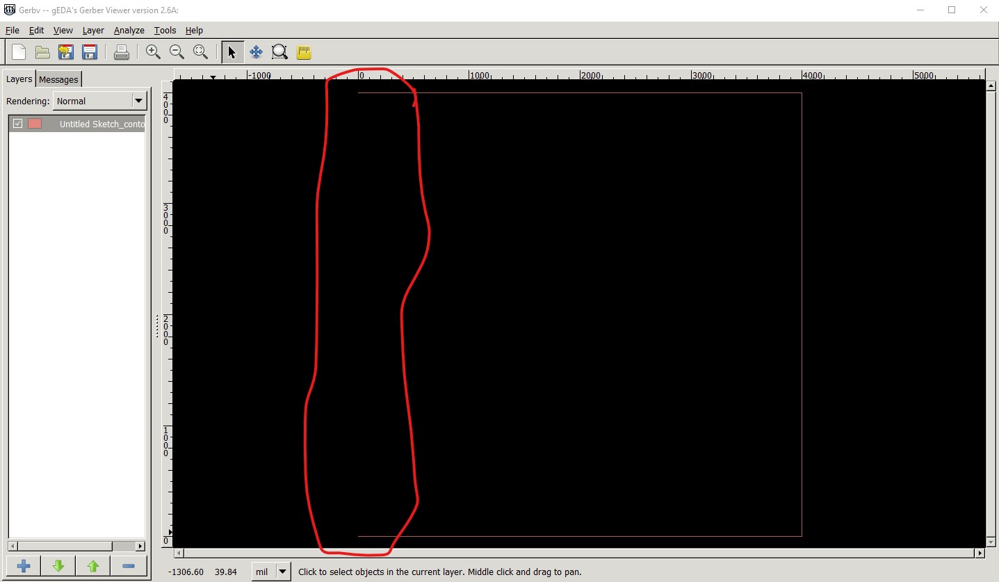
I’m exporting two boards with similar contour, only dimensions are different. One is exported well, the other one contour is not closed. (Fritzing 0.9.3)
These contours are produced with generated svg files, which means their code are really identical.
Can someone have a look and tell me where I’m wrong ?
3a: Failing

<svg height="50mm" version="1.2" viewBox="0 0 622.8 360" width="86.5mm" x="0" xmlns="http://www.w3.org/2000/svg" y="0">
...
<path d="M 117,63.4
		a 14.4,14.4 0 1,0 28.8,0
		a 14.4,14.4 0 1,0 -28.8,0 z
		M 477,296.6
		a 14.4,14.4 0 1,0 28.8,0
		a 14.4,14.4 0 1,0 -28.8,0 z
		M 0,0
		h622.8
		v360
		h-622.8
		Z" fill="#1F7A34" stroke-width="0"/>
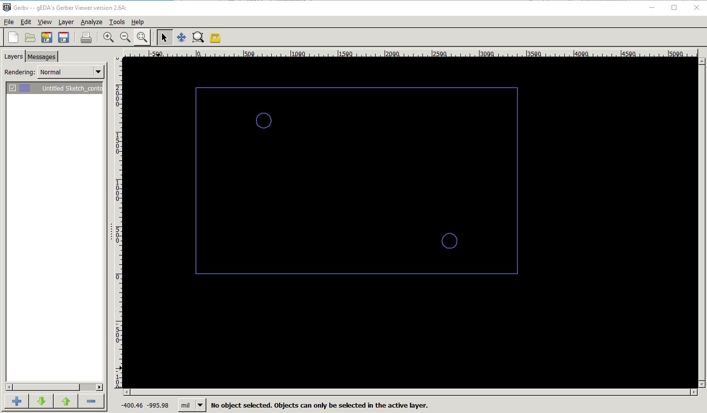
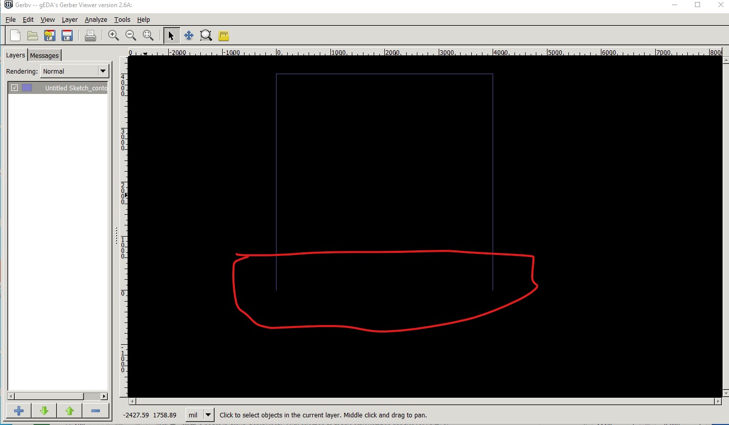
6a: working

<svg height="98.7mm" version="1.2" viewBox="0 0 596.9 710.6" width="82.9mm" x="0" xmlns="http://www.w3.org/2000/svg" y="0">
...
<path d="M 104,49.3
		a 14.4,14.4 0 1,0 28.8,0
		a 14.4,14.4 0 1,0 -28.8,0 z
		M 464,661.3
		a 14.4,14.4 0 1,0 28.8,0
		a 14.4,14.4 0 1,0 -28.8,0 z
		M 0,0
		h596.9
		v710.6
		h-596.9
		Z" fill="#1F7A34" stroke-width="0"/>
	</g>
The board is basically a svg path (with holes using arcs ‘a’). To make sure it’s closed, I use a Z command to end this path, which works well on the 6a board, but not on the 3a one.
thanks