Hello Peter.
Thank you again for your efforts. I’m not sure if I should like the squared pin 1, but hey, your graphics - your rules 
May I kindly ask you some questions as I would like to learn more about part design?
a) How do you achieve the grid alignment in Fritzing?
I see that the top/left pin is at 50/50 (I assume 51.041668 is just some mismatch) but what measure keeps it perfect in the 100/100 mil grid of the PCB view? Based on the numbers I would expect, that the part aligns in the middle of the box - not at the corner. I don’t find any hint in the XML to get that offset from 50 to 100. How do you do that?
b) Is there any reason why you draw the parts in “landscape” not in “portrait” dimensions? Portrait mode will give pin 1 the position top left.
c) hole measurements in general are miracle to me
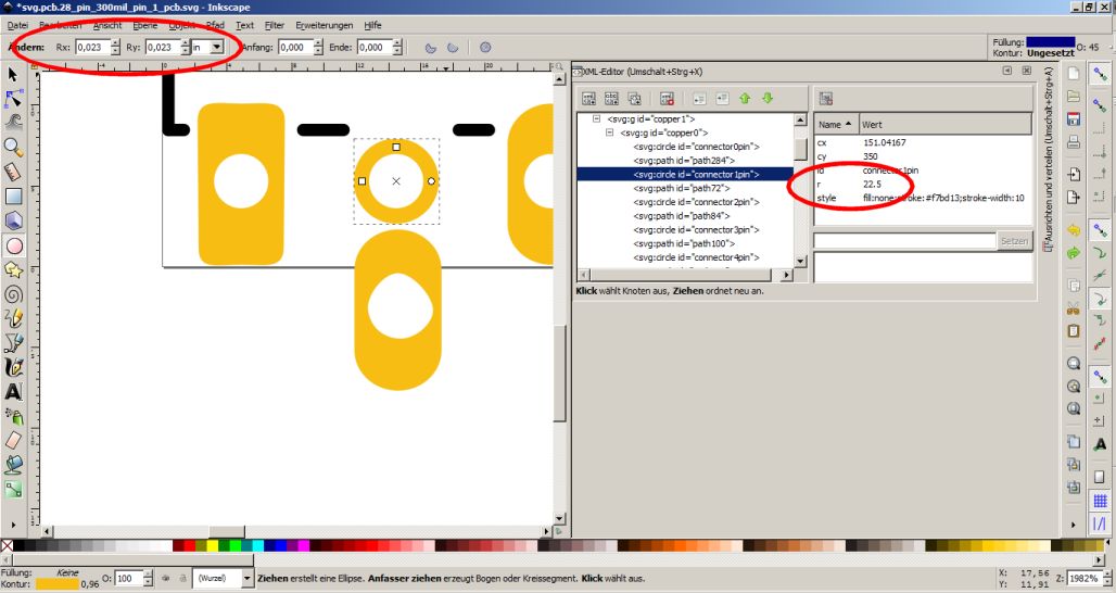
the holes are circles defined with r=22.5 with stroke 10. That should be 22.5*2=45mil Minus 5 for half the stroke (?) leaves 40mil = 1,016 mm as drilling hole? Is that correct ? The fab will produce a 1mm hole?
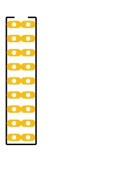
The reason I want to clarify: I want to make a part with two rows in line (100mil) and the oblong pads are to large for a 100mil grid. Even the round standard header holes are to large for routing standard wires between them. So what would be the best hole definition for a 1mm header? To be precise: the header measures 0.64mm/0.025mil. Should I just take the r=22.5 with 10mm stroke - but that’s against the “fritzing graphic standards” as they suggest 20mils at least. source: http://fritzing.org/fritzings-graphic-standards/

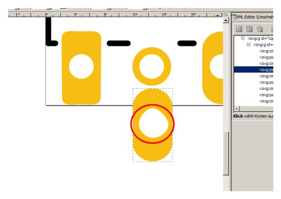
d) i found that the hole in the pad is not really a circle, it’s more like a Easter egg ;-). I know it’s already in the very first sparkfun part, but just want to warn you if you want to do more parts with that pins (and I see even my generator generates Easter eggs).


