Has anyone got a fritzing part for the G6K-2F-Y (SOP) and G6K-2P-Y (DIP) Relays?
I found an Omron part but it’s a standard 2.54 pitch (non -Y) - but every relay I can find available on AliExpress is the -Y version which has slightly different pin spacing!
Looks like my Fritzing got muddled (or my senior brain did) - I apparently have 2 G6K relays in my parts bins but I thought I only had 1. What ever that other one was, it was not the one imported from your reference link! Somehow I got in a right muddle there!!
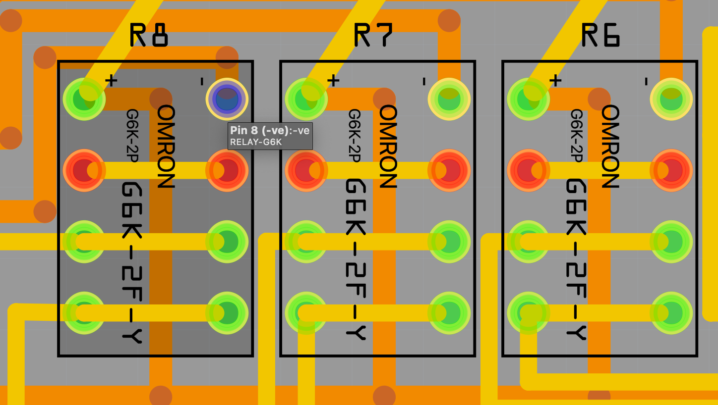
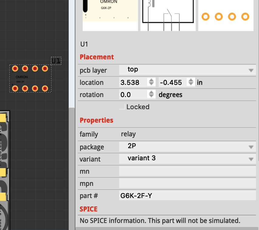
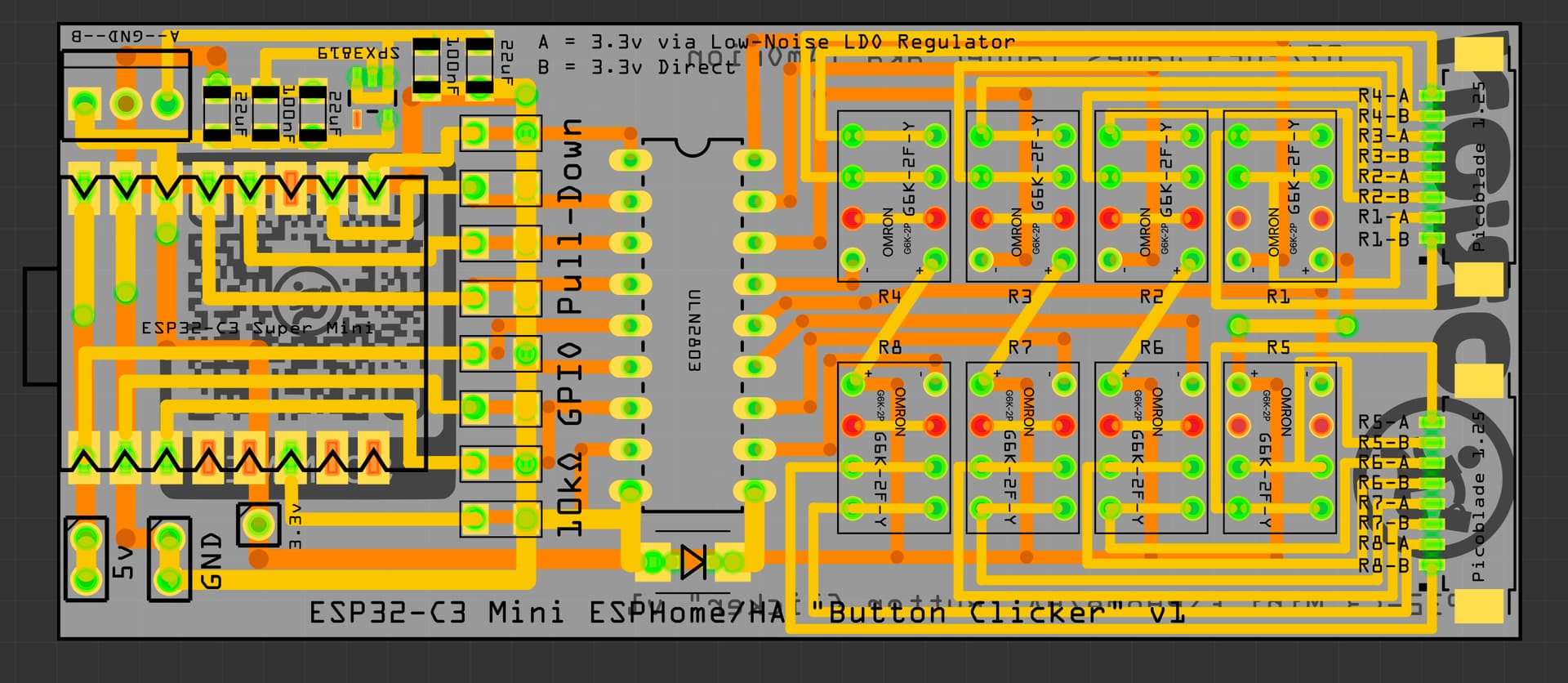
I have now found the SMD version after I removed what I thought was the only G6K I had in the bins, tried to re-add it and it wouldn’t let me saying it still existed (after a program restart) - I then searched all bins and found that one - that correctly has your name in the metadata, whereas the one seen in my pcb screenshot in previous posts had a different name in the metadata so obviously a different part.
Yeesh, sometimes I annoy myself so much ha!
A THT version would still be handy as it saves me adding loads of vias but I can still do it for this project
It is easy enough to do a tht version of the part. The layout is much the same. It is possible the first part you have is the tht version referenced in the same post, it is someone else’s on github and is tht although I didn’t look at it closely to see if it was right I’ll make a tht version and post it in a bit.
You’re absolutely correct, the github one by ‘houtbrion’ was the one I was using that is THT 2.54mm pitch! Ooof I’m such an idiot! What’s worse is I can now see I had already downloaded both the github one and your one 2 weeks ago, I must’ve got distracted and got myself in a muddle and not realised clearly.
Out of curiosity, since you seem well versed in Fritzing, or at least enjoy it and the parts creation etc - does that mean you have good knowledge of PCB Design as well? I always see “arguments” about right angles in PCB traces but I gather the general consensus these days, technology being much more advanced than 20 years ago, is that for hobbyist stuff or even non mission critical that doesn’t have any highly sensitive signal stuff should be fine - I’m curious as to your opinion?
I’ve never used the 45 degree angles you see often in KiCAD/Eagle/EasyEDA designs etc but I’ve also never had an issue (that I know of) in the years of doing random PCBs with right angles etc
As to traces at 45 degrees, it only really matters with rf and for EMI suppression, so for hobby use right angle is fine. I do 45 degrees simply because it is best practice and is easy to do.
Ah that’s fair enough. Good to know too, thanks for the input/info
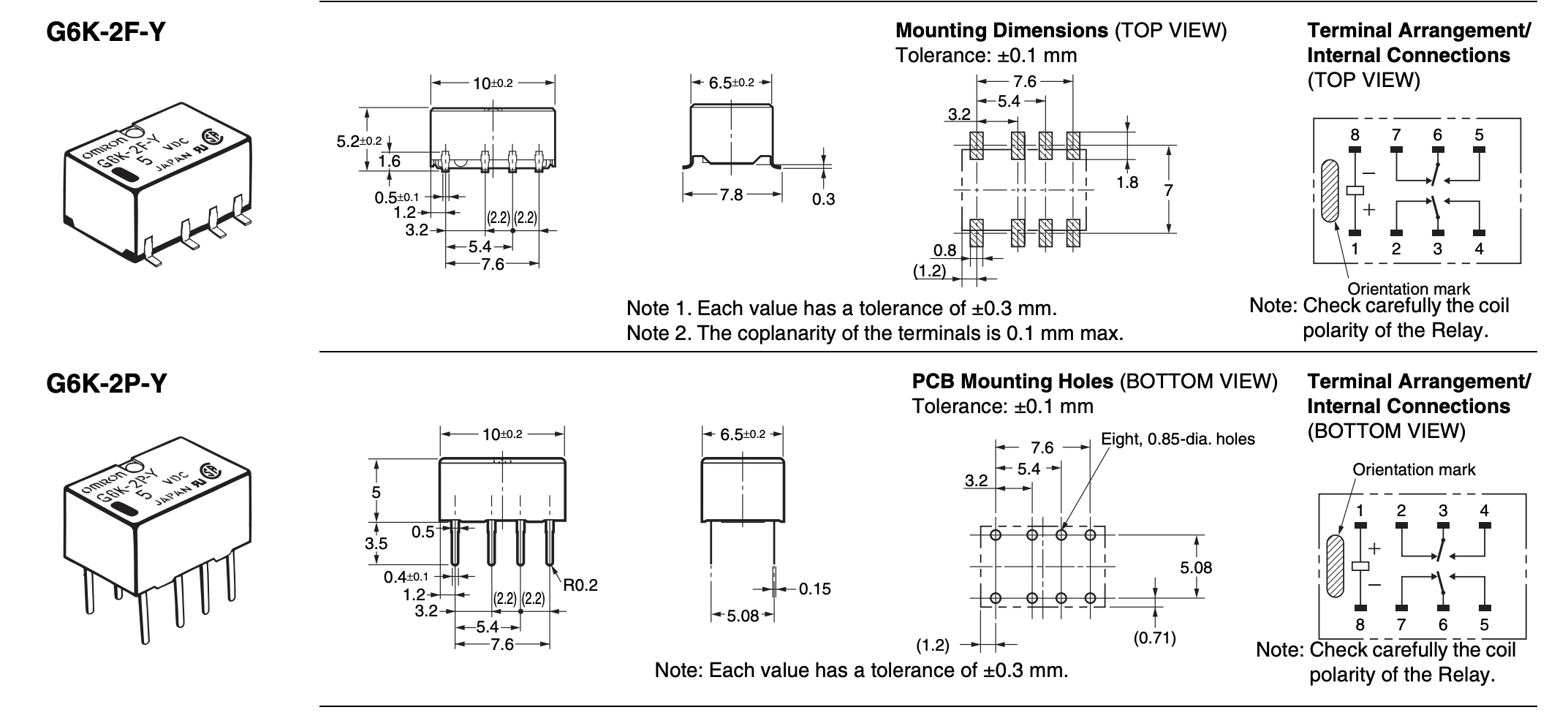
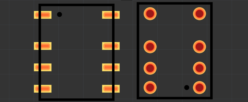
Edit: @vanepp I think the pin designation and the dot marker needs rotating 180.
The ‘top’ 2 pins that have the 3.2mm spacing to the next pins are the coil + and -.
(Unless I’m misreading the datasheet)
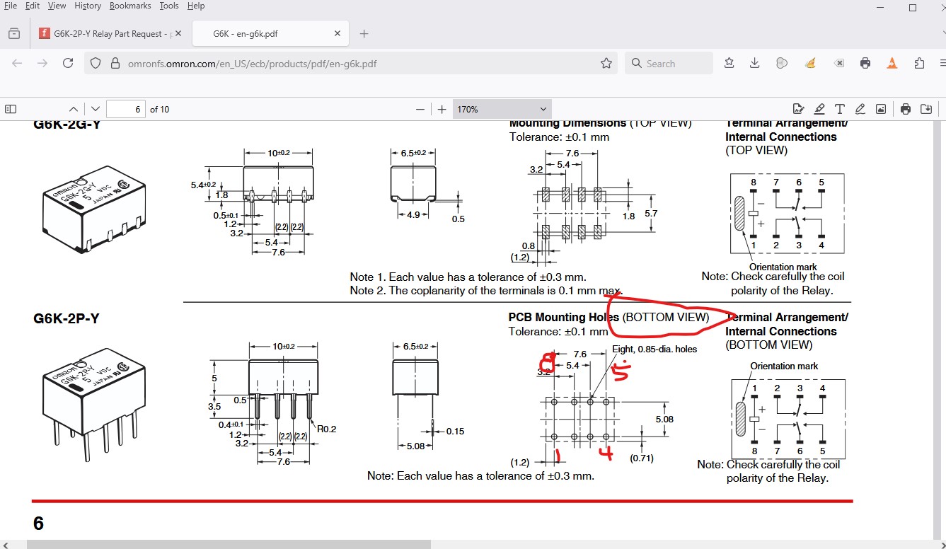
I think the original one is correct as the data sheet is shown bottom view but Fritzing uses top view so needs to be inverted (I assumed vertically since that makes the pins in the correct order although it could be horizontal, that seems unlikely.)
oof, I tell you what, the longer I look at that data sheet the more confused I get!
The first pins with the 3.2mm space to next pins are def the coil according to the Orientation Mark (meaning your black dot is on the wrong pin) - I will double check when I have the THT version in my hand. Currently awaiting delivery - takes about a week normally from AliExpress