I have a working prototype and want to make it as small as possible.
Please, see the image in attachment.
The device is attached to a beach racket and is used for game play measurements.
NRF24L01 wireless transceiver (for communication with a base station)
Switch (to set as player A or B)
A LED (to indicate a hit)
I’m not intending to sell it, and, if I ever do, it will be in very small quantities.
The price is not an important factor but the size and weight are.
What are the recommended steps to make it smaller and smaller?
I accept any kind of recommendations, from changing components, to assembling boards, to sending to a manufacturer, etc…
I’m a computer scientist with little knowledge about electronics.
Is Fritzing the right tool for me? If so, what are the next steps? Reproducing my circuit in the Fritzing breadboard view?
Breadboard and schematic in Fritzing is likely a good start. Off the top you can dump most of the bulk of the nano by building a board with a surface mount 328 on it and an external programming interface to get code in to it. You don’t need the bulk of the usb connection on the nano nor the connectors a pro mini may be a good compromise (it eliminates the USB and connectors but is prebuilt which can be an advantage). I suspect you may be best to stick with the NRF24L01 as a module, although there may be smaller wireless modules out there (you likely want a module rather than try and build you own though). You can save a bit of space / weight by using a lm339 quad comparitor in place of the dual 293s in use for the microphone and vibration sensor and may be able to eliminate the pots (reduces the size and weight) by selecting appropriate resistors for what you want to do. The switch and led are both easy. I’d say if you are a beginner that Fritzing is likely a good choice as it is easier to learn than the more complex EDA programs and should do fine for this project. There are schematics on the net for all of the parts and modules involved which makes life easier.
Wow.
Using those modules is the easiest because it’s just a matter of connecting them. From what I see you can’t stack them because of the VR pots, so they will have to be laid out flat making it large.
Getting the circuits off each module and transferring them to one PCB is going to be smaller, but a lot of work.
Breaking down the modules to a base sensor level might be possible, but that is going to take more work if it’s possible at all.
Thanks for the quick replies, I’m very excited about this project.
After studying the process a little bit more, I’m thinking of first getting a solder-able breadboard and do all the soldering myself also using the pre-built modules. Then, I’ll switch to a Pro-Mini before settling on the surface mount 328.
I’ll probably need the pots in order to adjust to the environment and racket material.
The three modules (mic, vib, nrf) seem to be already tight, I’m not sure if it’s worth transferring them to the PCB.
However, I couldn’t find any of the three modules on the “Parts” tab of Fritzing.
I believe they use standard connectors, but I don’t know exactly what to look for in the library.
Thanks
Because FZ is the only EDA with breadboard view it’s hard to get parts, ie, low uptake low demand. Other problems is that hard to make modules in FZ even if you know how, because it takes a lot of drawing, and new ones appear every day so it’s hard to keep up.
Also all made parts are not stored in FZ so you have to do a Goo search to see if someone has made them. I usually search part names and add Fritzing.
I’m similar to you but a Mech Eng with only 2 years in electronics, so I’m no expert, but I think there are micros with builtin WiFi that use the Arduino IDE that would save space. Maybe Wemos 8285, but I don’t know because there are too many and types and I don’t follow any other micros other than the Mega2560.
I watch Andreas Spiess, but I don’t know if any of his stuff will help because I don’t understand most of it.
He has a Sonoff SC hack series and with a design of a made motherborad with modules attached, which should be like yours.
there are 3 NRF24L01 in parts (enter NRF24L01 in to the search window and press enter)
the nano and pro mini are both in arduino in parts as are switches and leds. There doesn’t appear to be a KY-038 any where but it is easy enough for me to make one. Once you have adjusted the pots for a particular racket do you need to change them or does the setting stay the same? If the setting doesn’t change you can replace the pot with fixed resistors (and there are smaller trim pots as well) which would save some space. I think your plan to start with the modules on a breadboard is a good one, but I expect a custom pcb could be made to save a fair bit of space with some work if needed / desired.
EditL here is a part for the ky-038 so now everything should be present.
I’ve read somewhere that NRF24L01 has much lower latency than WiFi. I really need very low latency.
Forgot to say that I did use the search window, but my NRF24L01 has 10 pins and is different from those.
(And that I could find the SW-420 on the Web).
They make smaller pots that the square ones used on the boards but if you don’t need variable after calibration 2 fixed 604 smd resistors are even smaller. The microphone on the ky-038 is about .4in in diameter, but they make (for more money and with somewhat less sensitivity) ones down to about .2 in diameter. So it should be possible to save space by going custom. Do you need bidirectional communication? I suspect that some of the 433 meg rf stuff is probably even lower latency (but less robust as well) than the spread spectrum stuff like the NRF24L01 or wifi and may be somewhat smaller (but perhaps not bidirectional). If you have the spec sheet for the NRF24L01 module you have I can modify one of the current parts to match easily enough I expect. Best bet is probably try it with the modules to start and if that is too big then start looking at making a custom board as that is going to be more work than the modules.
I don’t need bidirectional communication. I only need to transmit.
I tried some cheap 433MHz modules but they were very unreliable, so I gave up for a while.
But you are right, if I find the NRF24L01 too big, I may reconsider other alternatives.
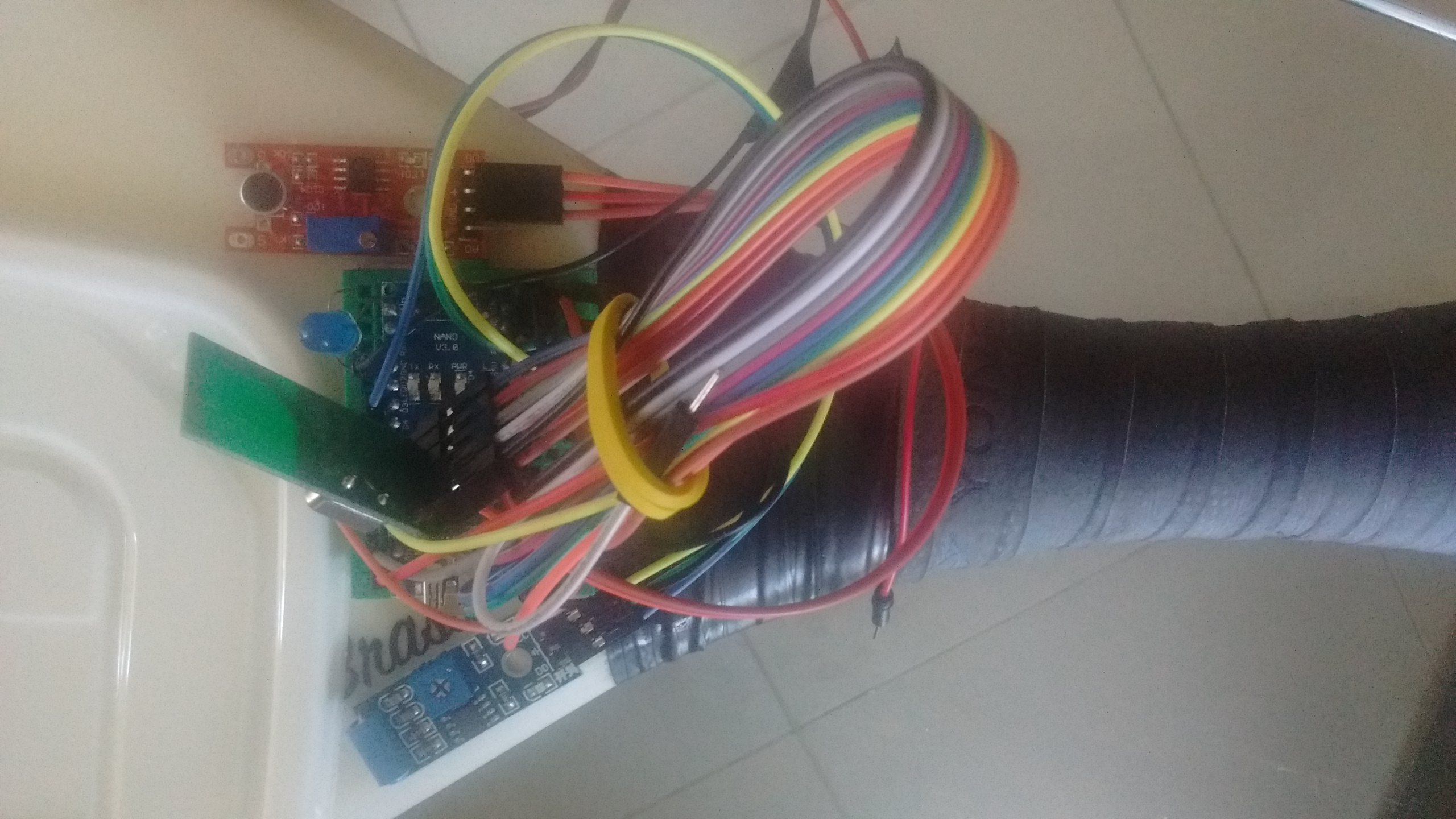
I have updated my project.
I removed the microphone and vibration sensors in favor of two Piezo sensors (one for each side of the racket).
Now everything fits in a 4x6cm board.
Any recommendations for producing a prototype PCB?
What about going further? How feasible is to design/produce a project using SMD technology for small-scale demands?
I was thinking if it would be possible to break the modules and inline them all in a single board.
I’m sure I cannot do it myself, but wonder if it would be feasible to pay someone to design this.
I need very small latency, I think WiFi would not work for me (also battery).
I couldn’t find a SoC with Arduino+NRF. That would be perfect for me.
You may not need to. I assume the wireless module is already small (most I’ve seen are) so you probably won’t save much space there and they can be tricky to design, so using a working one is a better bet. As far as I can see you are using 8 I/o pins so a 328 is overkill a ATtiny104 comes in a 14 pin SMD package with an internal 8 meg oscillator and 12 I/O pins. That would eliminate most of the Mini (you would need to provide the pins for programming it and probably a programmer as I doubt it supports the arduino boot loader) but it would reduce the size a lot. You should be able to put it under the NRF board (as other than its connection pins that is waste space on the pcb that could be recovered) either with the chips under the NRF or better on the other side of the board from the NRF. If you use the other side of the board from the NRF you could move all the pots and other stuff there as well and reduce your size to the size of the NRF module I expect although the board gets a little (but not all the much) wider. You may need to add a voltage regulator or a boost/buck power module to stabilize the battery voltage (which is currently done by the pro mini I expect) but that isn’t too difficult and may not be needed at all depending how the NRF module is about battery power (i.e. does it want exactly 3.3 or 5V or will it be happy on a battery, the CPU is happy with battery I think). So you would end up with what amounts to a daughter board the same size as the NRF board (and some of them are pretty small from what I see on Ebay) that connects to it via the NRF connector which should reduce your size by about 2/3 I think. As to assembly, I have seen ads from the PCB houses for boards plus assembly but have no experience with them. Hopefully someone else can comment on how they are at small volumes (I expect somewhat expensive because of setup costs but I really don’t know).
I don’t know because they say they are both WiFi, and the way the ESP’s dominate IOT I would have thought it would be way ahead in performance. Plus you get the micro all in one.
They are both wifi sort of. The Esp is 802.11b/g but I think the NRFs use a proprietary protocol of their own not 802.11 and thus technically aren’t wifi because they won’t interoperate I don’ think although I’ve not actually tried them just seen the docs.
If you don’t mind switching processors to the 8051 (which is a downgrade from an avr ) there is a soc solution in the nRF24LE1. I expect that you would need to change from gcc to sdcc (and 8051s are a pain in sdcc) for a C compiler but it would reduce your space considerably. Modules look to be about $4 on ebay. A dev kit from Nordic is $149 out of digikey and at least someone on Sparkfun mentioned success using SDCC as their compiler (keil apparently also supports it, but they are expensive!) so it looks like there is support of sorts around for open source tools.
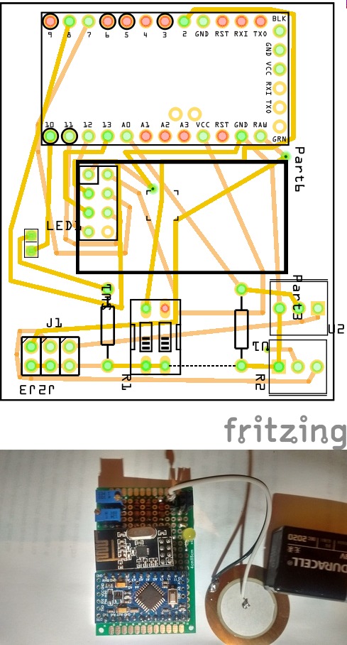
I followed your advice and put the Mini-Pro under the NRF module and now I only need 4.0cm x 2.4cm.
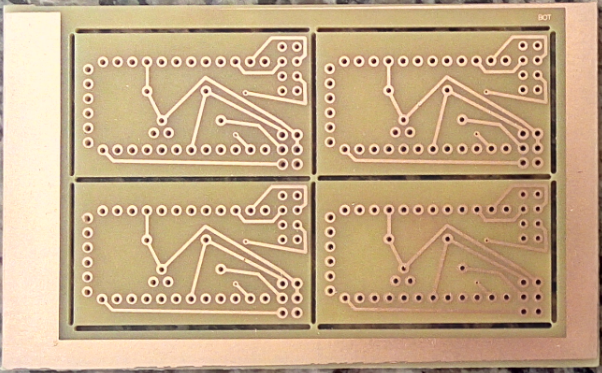
I ordered four prototype PCBs which are about to arrive:
I also ordered a even smaller Li-Po battery.
I can still switch to a ATTiny to save more space, let’s see.
Thank you. I think this sensor would not allow me to distinguish between racket movements and ball hits. But it’s nice to have it in mind for extra functionality.

 ) there is a soc solution in the nRF24LE1. I expect that you would need to change from gcc to sdcc (and 8051s are a pain in sdcc) for a C compiler but it would reduce your space considerably. Modules look to be about $4 on ebay. A dev kit from Nordic is $149 out of digikey and at least someone on Sparkfun mentioned success using SDCC as their compiler (keil apparently also supports it, but they are expensive!) so it looks like there is support of sorts around for open source tools.