It should work fine as is, but here are some improvements. Starting from the original svg
FritzingCheckPart.py (an as yet unreleased development version) has this warning
Warning 32: File
‘voltreg.svg’
At line 12
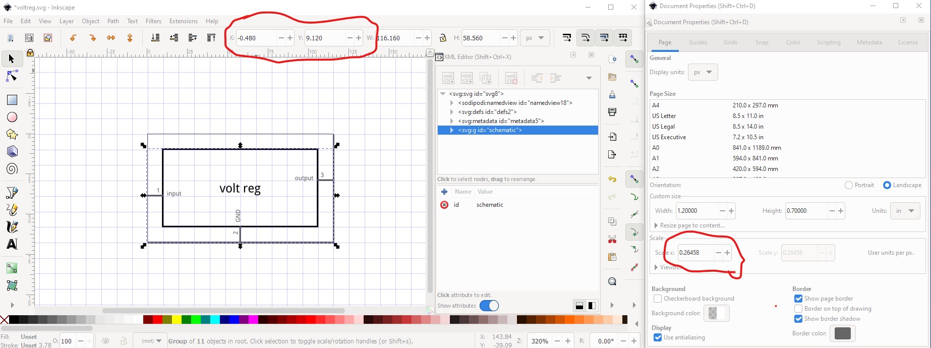
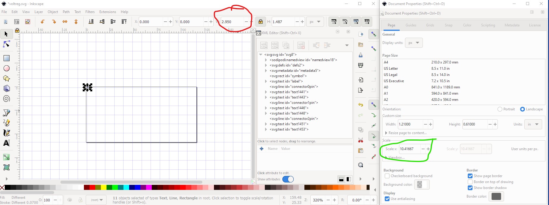
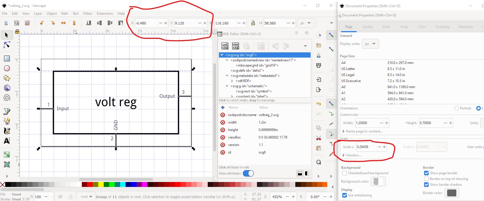
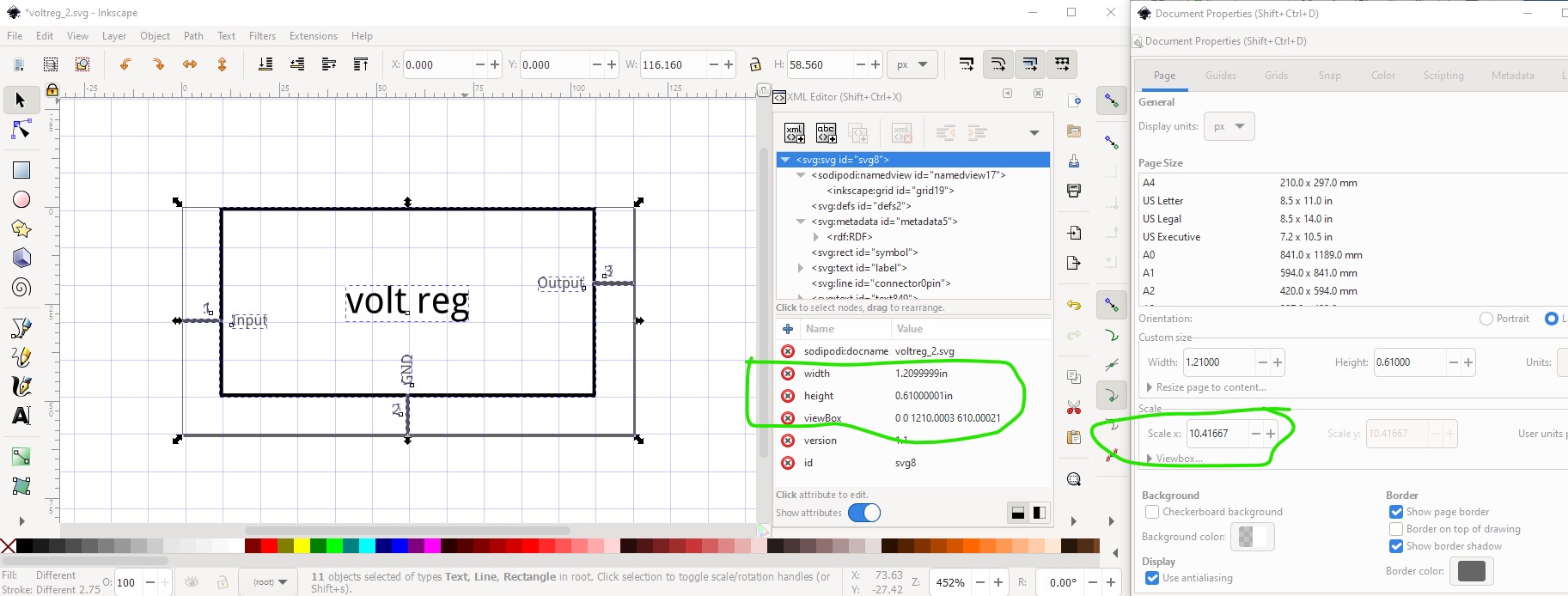
Scale is not the desirable 1/1000 ratio from width/height to
viewBox width/height.
to fix that
edit->select all
edit->resize page to selection
select group schematic in xml editor
Object->ungroup
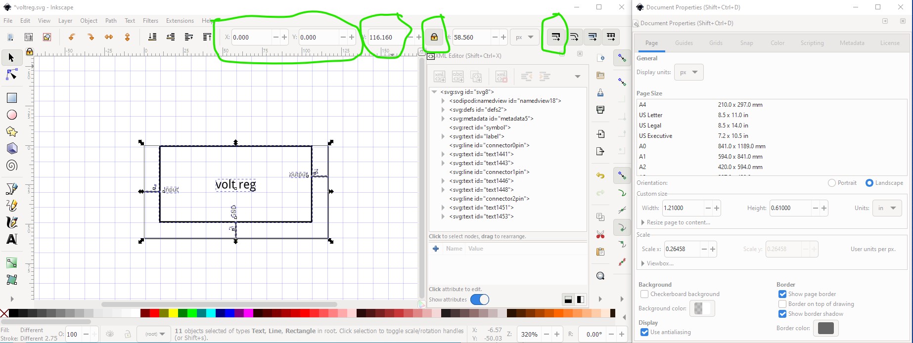
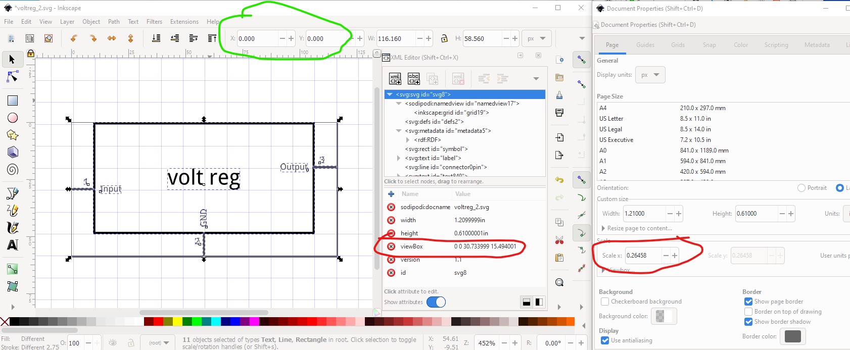
to resize the view box to start at 0 0
then lock width to height (to keep circles circles instead of an ellipse due to floating point roundoff), enable “when scaling objects scale stroke-width proportionally”
FritzingCheckPart.py (an as yet unreleased development version) has this warning
Warning 32: File
‘voltreg.svg’
At line 12
Scale is not the desirable 1/1000 ratio from width/height to
viewBox width/height.
to fix that
edit->select all
edit->resize page to selection
select group schematic in xml editor
Object->ungroup
to resize the view box to start at 0 0
then lock width to height (to keep circles circles instead of an ellipse due to floating point roundoff), enable “when scaling objects scale stroke-width proportionally”
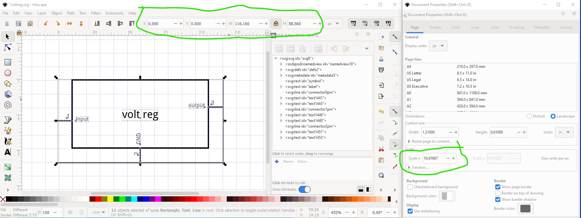
now in the tool bar set width back to 116.160px to retore the image to the correct size then unlock the width/height and disable scale stroke-width (my usual setting)
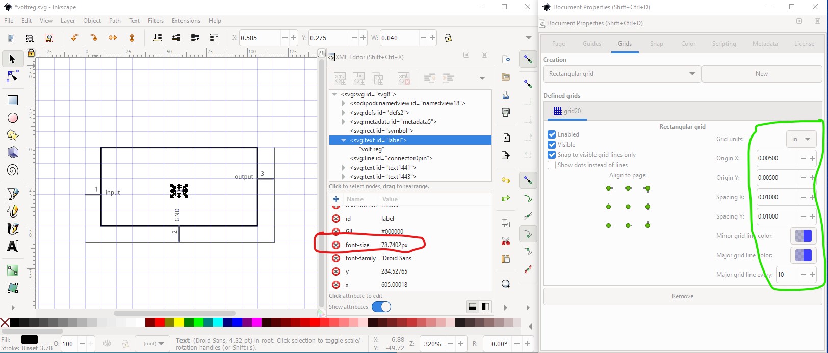
Now on to the elements of the svg. First here is the grid settings I use. The x and y origins are offset 0.005in, so with the standard 10thou stroke width the grid lines are in the center of the 10thou line and lines should be on an even 0.1in boundary.
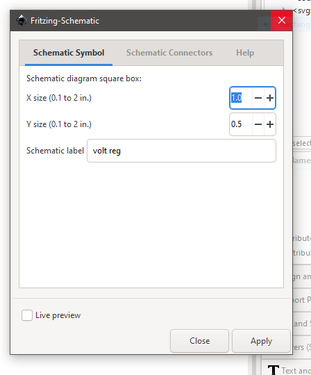
Here I have selected the label text field. The font-size is currently 78.7402px, that should change to 60px (as specified in the graphic-standards document here
https://fritzing.org/fritzings-graphic-standards
the part file format document here is also useful for this
The rest of the setup looks fine. The fill is #000000 as it should be.
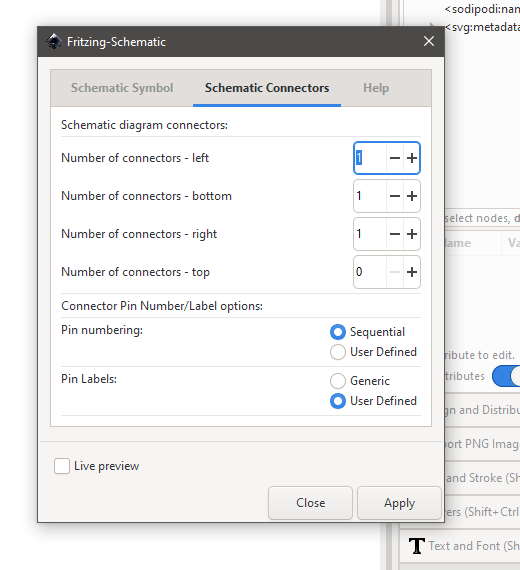
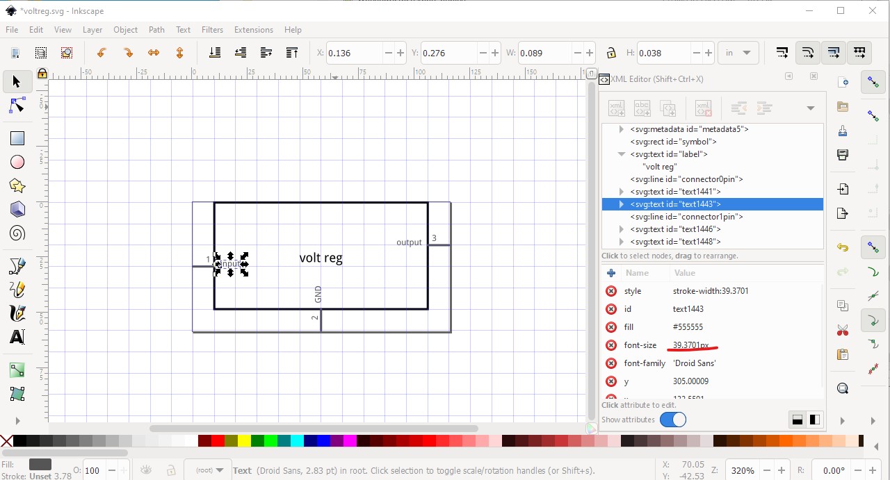
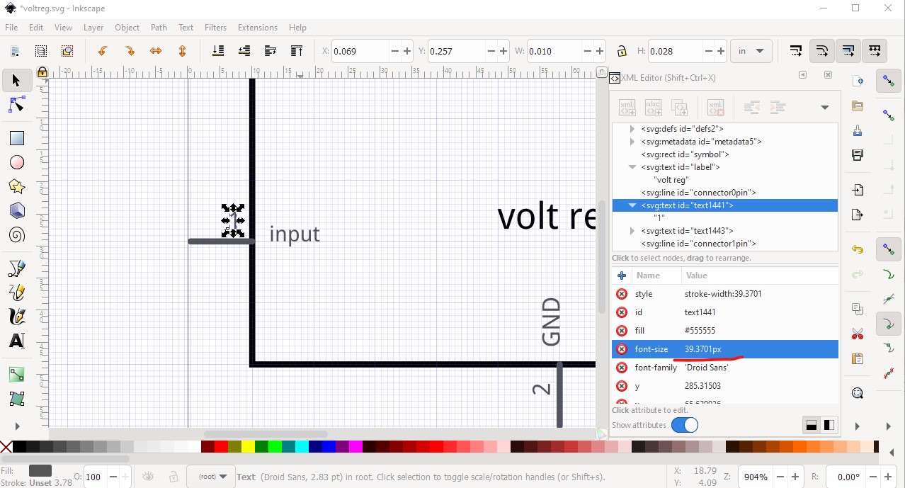
On to the pin label. Again it is mostly good, the font size should change from 39.3701px to 35px (and desirably lose the px, but I don’t think Inkscape will do that!) The fill is the correct #555555 value called for by the graphic standards.
The pin number needs to drop to 25px to match the graphic standard.
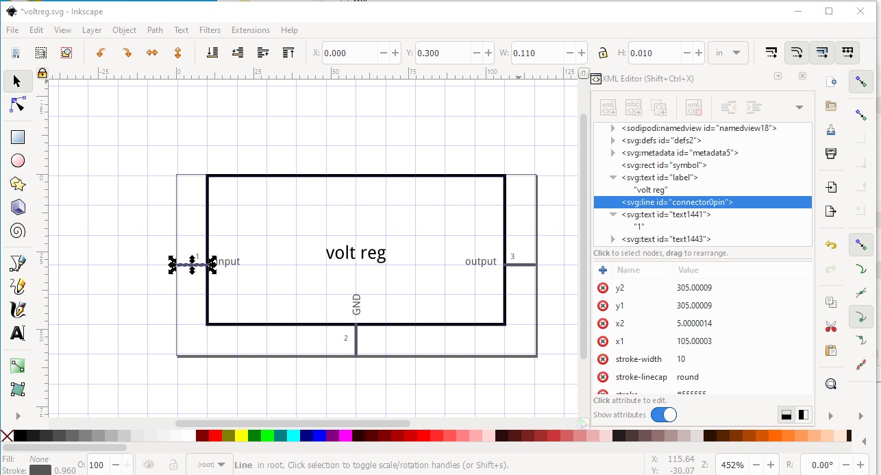
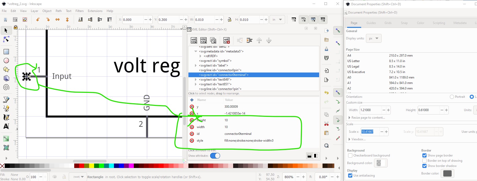
the ground pin (and top/bottom row pins in general) are more of a problem. I prefer to have all the text readable the same way, but with long pin labels your current method is probably better. I added a text-anchor:start to the label (so more text will start at the correct place and grow upwards and centered the text on the middle of the pin. For text on the top, the anchor needs to be end (so the text grows down.) I rotated the pin number 90 degrees to match the rest of them (as pin numbers are typically small enough to not be a problem.
The pins are correctly aligned on even 0.1in boundaries, I usually use a pin width of 0.105in rather than 0.110in but either will do. All that results in this svg (trying to upload the svg directly got
so I zippeed the file as voltreg-improved.fzp (you need to zip it because otherwise the forum discovers that it is an svg and tries to render it with the failure above) and then upload the fzp
voltreg-improved.fzp (1.1 KB)
If you download and unzip this you should get my modified svg file.
Peter