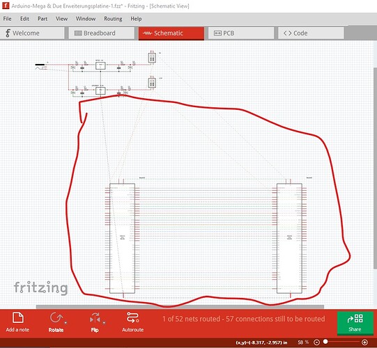
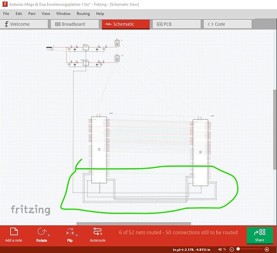
It appears to me that you may be not aware how autorouting works. It is necessary to have the sketch completely routed in either breadboard (which you don’t appear to be using) or schematic before autorouting pcb will work. In the Arduino-Mega & Due Erweiterungsplatine-1.fzz sketch schematic is not routed and thus autoroute doesn’t work. Here in schematic the traces to the two micros are not routed (they appear as rats nest lines because they exist in pcb.)
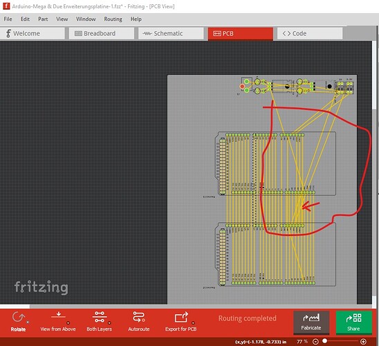
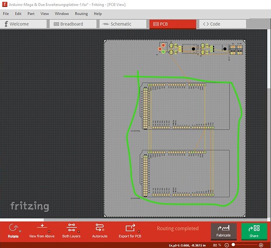
pcb appears to have been manually (and incorrectly as the traces circled in red are all on the top layer and thus will short!) routed.
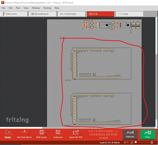
here I selected routing->select all traces and then hit delete to remove all the traces. Note there are not rats nest lines for the connections to the two micros because they are not in schematic or breadboard and now have been deleted in pcb so they no longer exist in the sketch!
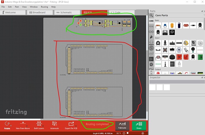
clicking routing->autoroute correctly route the board (indicated by the routing complete at the bottom)
but does nothing for the micros because the traces are not present in schematic. Here I routed some of the rats nest lines in schematic (I was too lazy to do all of them as required!) and then autorouted again (all of this is being done on Windows 10 on Fritzing 0.9.10!)
Then I autorouted pcb again and it also works correctly and adds the traces added in schematic:
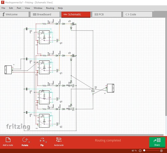
Doing the same thing to the Hochspanner.fzz sketch works correctly as schematic is fully routed and thus autoroute will do as good a job (which is typically not very good!) as it ever does:
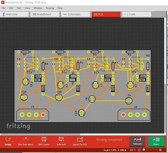
then delete all traces and autoroute pbb
Hope this helps!
via google translate:
Es scheint mir, dass Sie möglicherweise nicht wissen, wie Autorouting funktioniert. Es ist notwendig, dass die Skizze vollständig entweder im Steckbrett (das Sie anscheinend nicht verwenden) oder im Schaltplan geroutet ist, bevor das Autorouting der Leiterplatte funktioniert. Im
Arduino-Mega & Due Erweiterungsplatine-1.fzz Sketch-Schema wird nicht geroutet und daher funktioniert Autoroute nicht. Hier im Schema sind die Spuren zu den beiden Mikros nicht geroutet (sie erscheinen als Rattennestleitungen, weil sie in der Leiterplatte vorhanden sind.)
Die Leiterplatte scheint manuell (und falsch, da die rot eingekreisten Leiterbahnen alle auf der obersten Schicht liegen und daher kurzgeschlossen werden!) Geroutet worden zu sein.
Hier habe ich Routing->Alle Spuren auswählen ausgewählt und dann auf Löschen geklickt, um alle Spuren zu entfernen. Beachten Sie, dass es keine Rattennestleitungen für die Verbindungen zu den beiden Mikros gibt, da sie sich nicht im Schaltplan oder Steckbrett befinden.
Klicken Sie auf Routing->Autoroute, um die Platine richtig zu routen (angezeigt durch das vollständige Routing unten).
bringt aber nichts für die mikros weil die spuren im schaltplan nicht vorhanden sind. Hier habe ich einige der Rattennestleitungen schematisch geroutet (ich war zu faul, sie alle wie erforderlich zu machen!) und dann erneut automatisch geroutet (alles wird unter Windows 10 unter Fritzing 0.9.10 durchgeführt!).
Dann habe ich die Platine erneut automatisch geroutet und es funktioniert auch korrekt und fügt die im Schaltplan hinzugefügten Spuren hinzu:
Das Gleiche mit der Hochspanner.fzz-Skizze zu tun, funktioniert korrekt, da der Schaltplan vollständig geroutet ist und daher die automatische Routenführung so gut funktioniert (was normalerweise nicht sehr gut ist!), wie es immer der Fall ist:
dann alle Traces löschen und pbb autorouten
Hoffe das hilft!
Peter
