Hi - we’re developing some training materials around the Freenove ESP32-S3 Wroom board and the matching Freenove Breakout Board, which supplies LED port readouts, screw terminals and higher power output for motor control, etc. It is intended to match a 4D Systems Reptor-250 touchscreen display and controller for rapid prototyping of bioinstrumentation and other things.
This is part of the Biomaker training effort at the University of Cambridge (https://www.biomaker.org). We’re looking for any help with Fritzing parts that would allows to make better training materials - all open source. (Similar to: Document-your-project — Biomaker.org, and can be seen in the Biomaker Handbook online)
The relevant processor board and breakout board are:
- Freenove ESP32-S3 Wroom board, with:
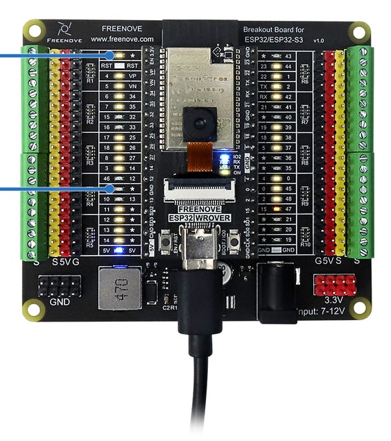
- Freenove ESP32/ESP32-S3 Breakout Board
Previous work, similar parts
The Freenove ESP32-S3 Wroom board is similar to:
ESP32-S3-1-N16R8-module (ESP32-S3 CAM development board WiFi Bluetooth module onboard ESP32-S3-1 N16R8 module dual TYPE-C interface.) by Peter Van Epp (vanepp in forums) (ESP32-S3 CAM papan pengembangan modul WiFi Bluetooth onboard ESP32-S3-1 modul N16R8 antarmuka TYPE-C ganda - AliExpress 44)
The Expressif chip is slightly smaller on the Freenove board than that shown on this existing part.
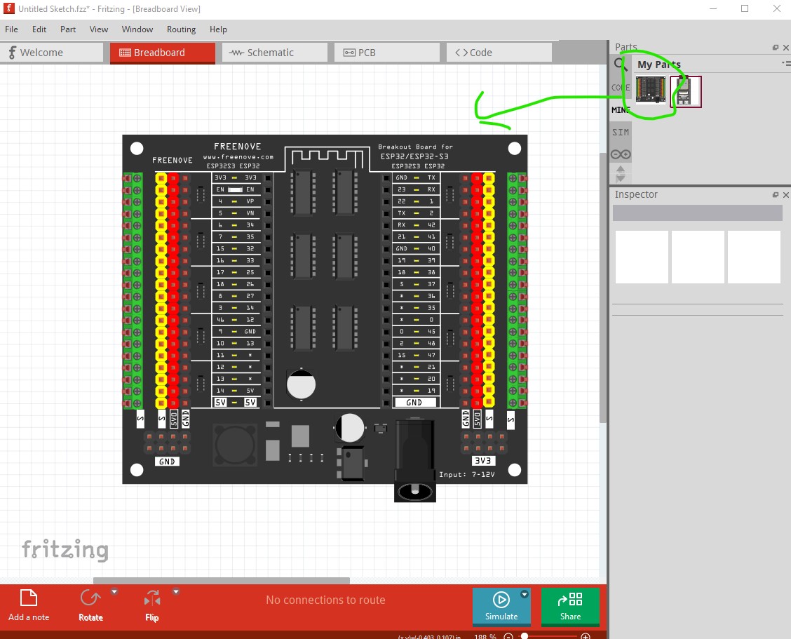
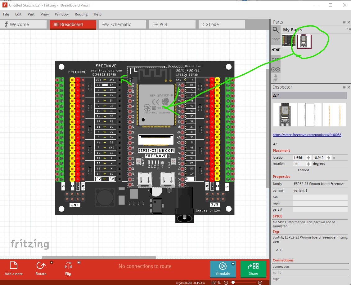
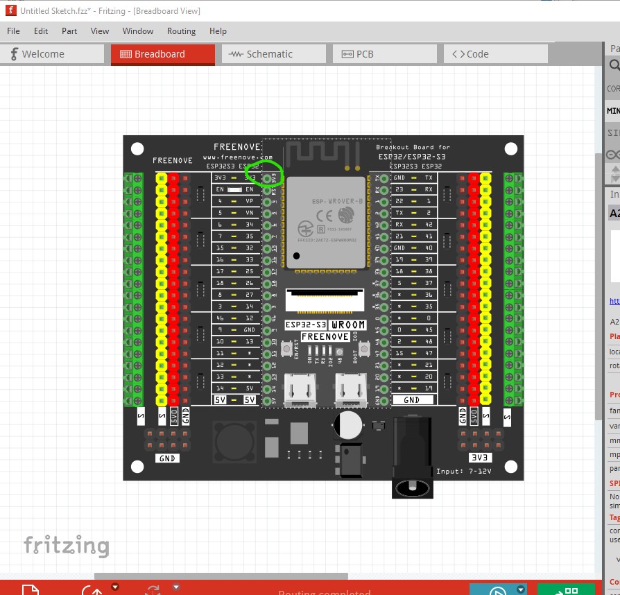
There doesn’t appear to be an existing part for the Freenove ESP32/ESP32-S3 Breakout Board.
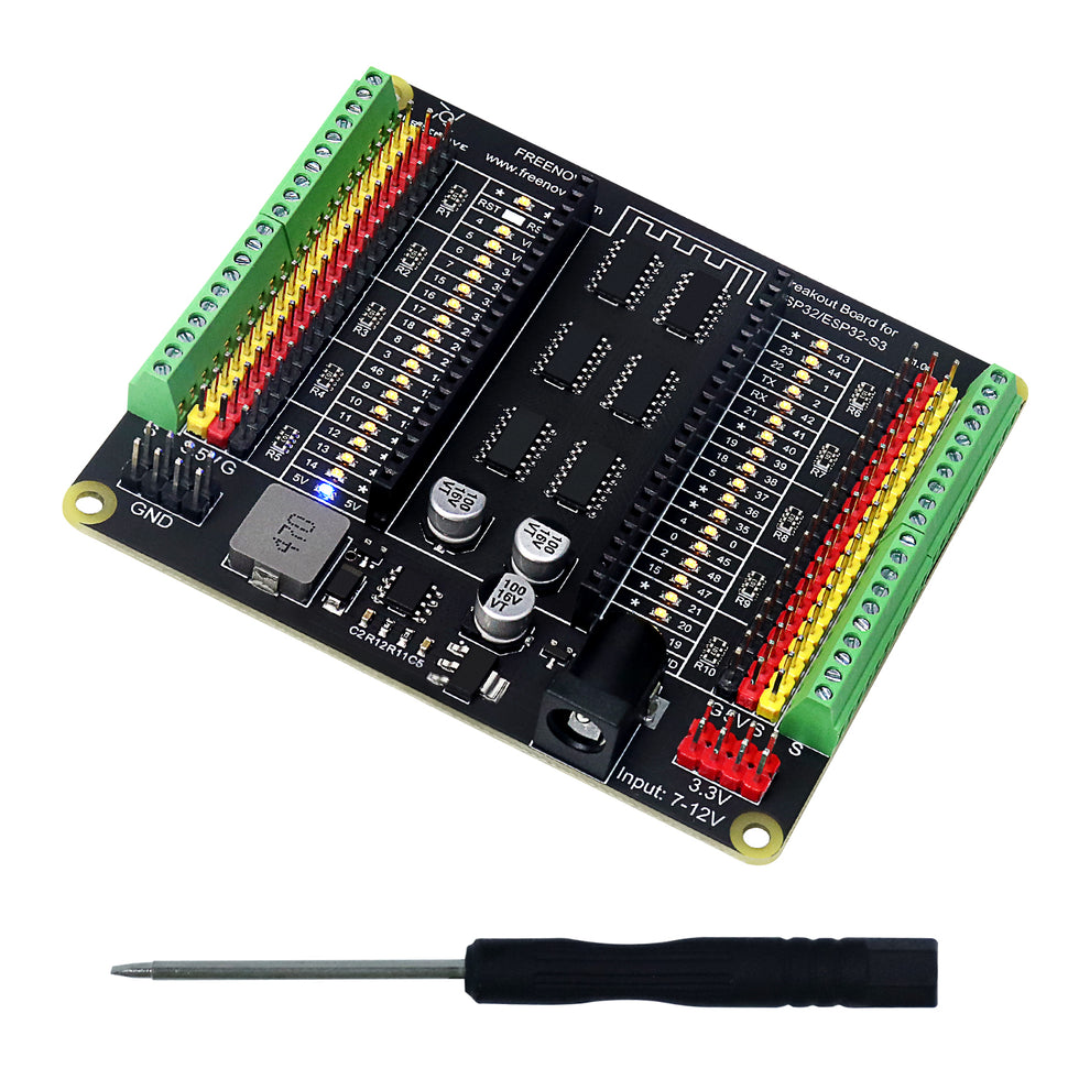
Top view
This picture shows the part from above, so that is easy to see were connectors should go, and which diameter they have.

Datasheet
The official documentation of the part manufacture is linked here:
Type
I did not read this
[ x] Breakout board, sub assembly, plug in module (A)
Antenna (AE)
Battery (BT)
Capacitor (C)
Diode (D)
Display (DS)
Fuse (F)
Hardware , mounting screws, etc. (H)
Jack, fixed part of a connector pair, header (J)
Relay (K)
Inductor, Coil, Ferrite bead (L)
Loudspeaker, Buzzer (LS)
Motor (M)
Microphone (MK)
Plug, moveable part of a connector pair (P)
Transistor (Q)
Resistor (R)
Thermistor (RT)
Varistor (RV)
Switch (S)
Transformer (T)
Integrated Circuit (IC)
Crystal, Oscillator (Y)
Zender diode (Z)
Other (please specifiy)
Footprint
E.g. SOT23-5 , TO-220.
This usually does not apply to breakout boards.
Thanks in advance for any advice or help with this. Best regards, Jim Haseloff.