When trying to vertical flip my PCB layout, I first selected it, then I wanted to tick “sticky” in the
Inspector but the Inspector turns blank after the select action.
What am I doing wrong? Or is this simple action not possible in Fritzing?
I don’t see any flip vert in FZ, you can only “view from below”. Insp usually goes blank when some thing is not selected.
Your best bet may be to upload the sketch (the .fzz file, upload is 7th icon from the left in the reply menu) and tell us what you want to do. With the sketch in hand one of us may know a way to do what you need.
Peter
If you are trying to view the pcb from a different perspective, without actually modifying it, then the Fritzing pcb view has an option to “View from Above” or "View from Below. That is effectively a horizontal flip, plus change which traces are “on top” in the view.
The Inspector window goes completely blank if nothing is selected. When you select the pcb, does it get a dashed border? If not, it is not selected. With the way parts can be stacked on top of each other, perhaps you are actually selecting something else.
If you are trying to modify the position of parts on the pcb, that is a different task, and Fritzing does not directly have that capability. Multiple parts can be moved at once by selecting them all (drag select, or muliplte (ctrl) select), then dragging them. A pcb board can be rotated, but not flipped. When the board is set sticky, the parts on the move (including rotate) with the board, but their position does not change relative to each other.
There are flip options on the part menu, but that applies to the currently selected (individual) part, and only if the part has been configured to allow it in the specific view. Schematic view normally allows flipping, and some parts for Breadboard view. I do not know of any that flip in pcb view.
Individual parts can be placed on the top or bottom of the pcb, which effectively flips them. Select a single part, then (in Inspector), select top or bottom in the pcb layer dropdown.
As vanepp said, we really need more information about what you are trying to do, and the pcb you are trying to do it with.
@ Old_Grey, vanepp, microMerlin:
Thanks for your responses. Yes, only a Part (otherwise it is greyed out)can be flipped horizontally or vertically when looking in “Part”. What I what to do is after making a layout for one (left)channel, just copy and flip it vertically to immediately have the layout for the other(right) channel.
After some fiddling I could not detect how to do this but microMerlin brought me on track with "…the Fritzing pcb view has an option to “View from Above” or "View from Below. "
I have to confess that I did not notice this possibility until microMerlin wrote this! (Must be my age  ) Why? Because I would expect another nomenclature: “Top View” and “Bottom View” as a more usual way to do this. Thought it was something else . I was wrong of course.
Anyway, when using this “View from below” > Select the PCB > rotate 180 deg. I finally get what I want. 
Problem solved.
Ahh, you said PCB and sticky(PCB term), so it sounded like the PCB.
View from below doesn’t flip anything, it’s just you looking up from below, ie everything looks reversed but isn’t. Rotate 180º will look like a flip if everything is symmetrical in the horiz plane.
Old_Grey, sorry for my late reply but I did not receive an email notification that somebody had responded. And… I never use Schematic or Breadboard. Only use the PCB.
Yes, first the “looking from below” and then rotate 180 degrees looks like a flip but in fact it is not.
Everything you want to do after that (copy and paste it into the “non flipped” pcb), will give you still that “looking from below” result. I expected that after the copy paste action everything will be handled as “looking from above” but it is not! Very frustrating that such a simple act as “flip vertically” or “flip horizontally” is not possible in Fritzing.
I think I have to live with it. Sorry that I cannot remove “Problem solved.” in my last response.
You could upload the .fzz with the 7th button above and maybe someone can think of something if they can see it, but if it’s non symmetrical I’m guessing you have to do it manually. If everything is snapped to the grid, you probably could just manually snap the parts to the oppose ends of the PCB fairly quickly.
While I don’t know of a way to flip pcb (I have never had an occasion to use it) I’d suggest as a test of whatever you try to export the pcb view as gerbers and use a gerber viewer to check the output. In this case that would show you that both boards are identical not flipped as you desire. The gerber output is typically what will be used to create the board.
Peter
If you want to design a pcb part for a stereo amp then you need also a stereo potmeter.
To solder that potmeter on the pcb then the potmeter pins are doubled for L+R channel.
So if you copy one channel pcb and flip that, you can immediately solder the potmeter pins
on the board.
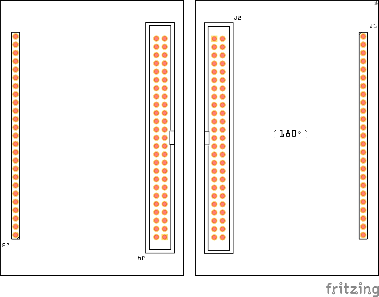
Like the example FOR ONE CHANNEL here:
ECC99-Tone-Control-Single-II.fzz (21.1 KB)