This is my first post here and I’m trying to create my first PCB. I have a working prototype of my system with a breadboard, but I would like to turn it into a PCB in order to minimize the weight.
Here are the components I am using/would like to use:
Seeeduino XIAO SAMD21 microcontroller. I believe this could be reduced to the bare essentials/pins that I actually use rather than the whole board, but I am not yet knowledgeable with how to do this.
MAX31855 thermocouple amplifier. This is so I can amplify the signal from a k-type thermocouple
2 DIP switches. This allows me to control which segment of code the microcontroller runs without requiring a code re-upload
A 3-pin, 2-position slide switch. This is intended to act as a toggle for a very small LiPo battery
JP2 connector. This is the part I am currently using, however, the actual part I need is a male Molex 1.25 mm (51021-0200) connector. Ideally this port would be mounted so I can attach/detach the LiPo battery easily.
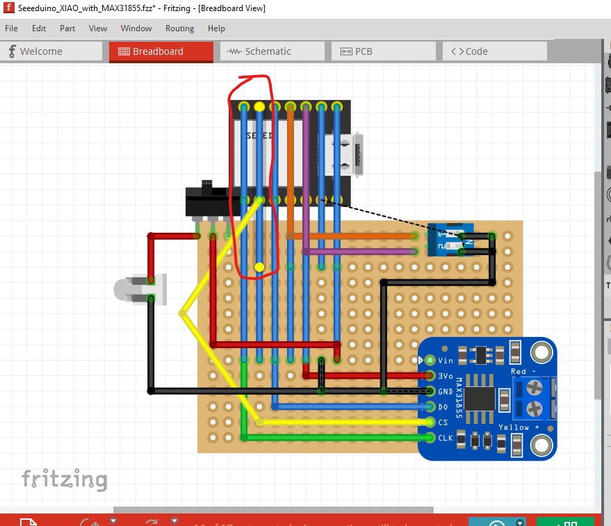
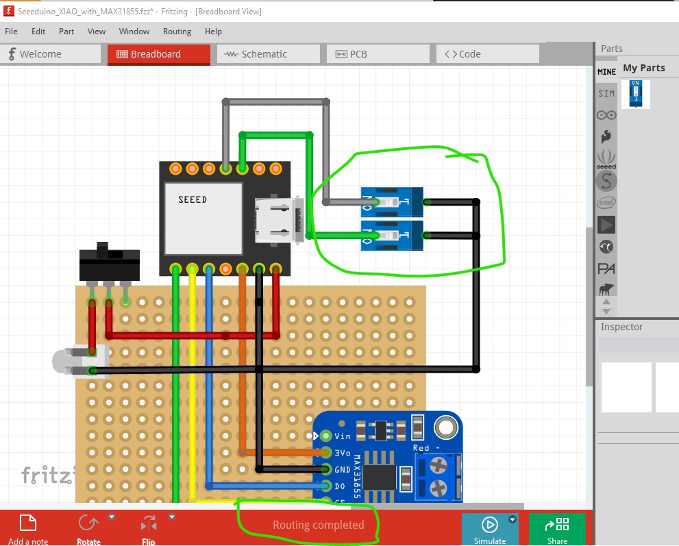
Here is a picture of the PCB I have but I will also upload the .fzz file:
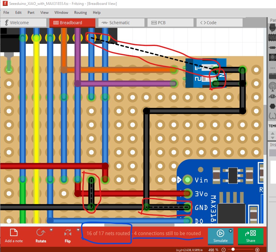
There are a fair number of things wrong here. Lets start with breadboard which is a mess. First is is not correctly routed, which means pcb and schematic may not be correct. at the bottom you see there are 4 unconnected nets. They are outlined in red (each has a rats nest line showing where the connection should go.)
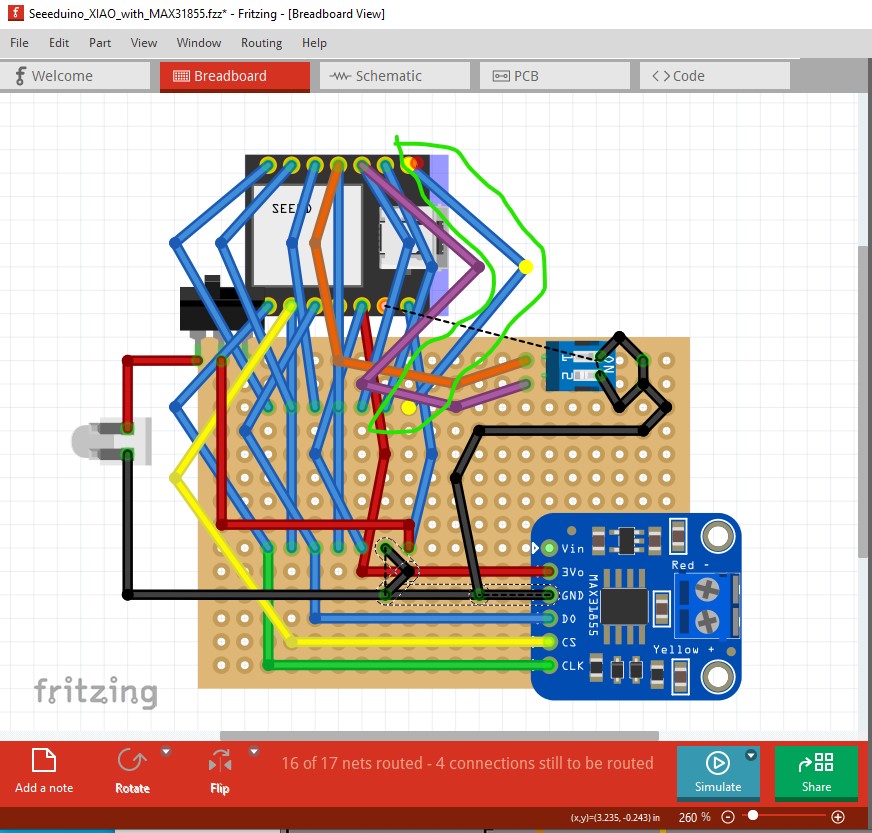
So lets go clean up breadboard. Here I dragged the yellow wire to the left to expose the wire under it, then right clicked on the top pin connected to the blue wire. That lights everything connected to the wire in yellow. Here we see there is nothing connected to it so this wire can be deleted as not needed. That is ends with yet another blue wire going past it indicates more problems.
so drag all the wires apart so we can see the unconnected wires and delete them. There are a lot of them all doing nothing except cluttering up breadboard.
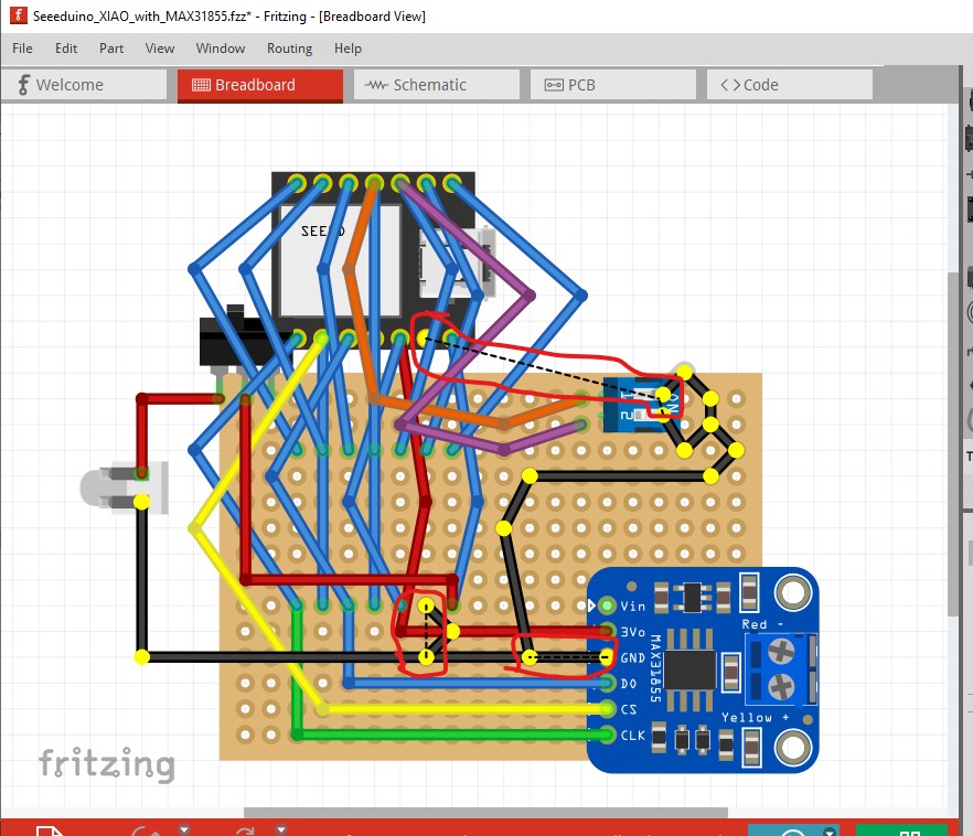
Here I right clicked on a ground pin and it lights everything that should be connecting to ground (even the ones without wires but with rats nest lines) yellow.
here we are looking at the 2 position dip switch (which is broken and needs replacing.) While the connection is showing as there, the wire doesn’t actually connect to the switch (but is close enough to make a connection!)
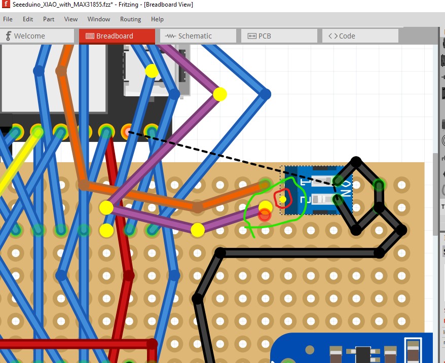
here is breadboard with all the unused wires removed and the dip switch replaced with 2 correct single pin ones (I eventually made a correct 2 position dip switch and replaced these two with it.) You see that routing is complete at the bottom of the screen. You can also see clearly where each wire goes which is vital to get the wiring correct.
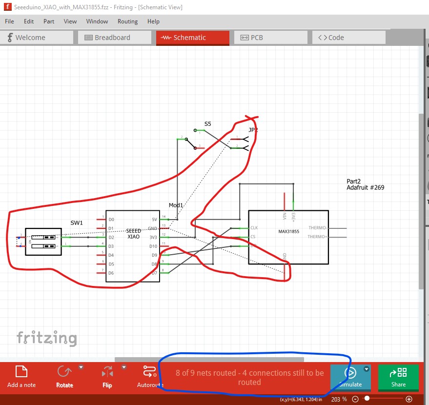
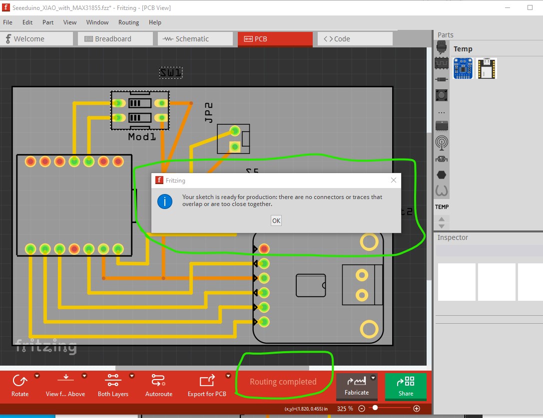
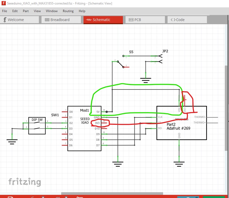
this sketch is your original circuit as wired but without the last error (explained below) corrected. Here I reduced the size of the pcb as far as possible to save weight. Even more can be done if required.
Now this is schematic completely routed with the final error corrected. That error is that the 3.3V pin on the MAX31855 module is an output (from an on board voltage regulator) not an input. The board is expecting 5V on the VIN pin to power the internal regulator to produce the 3.3V that they need for the themocouple or the thermocouple chip. It may work successfully with the original layout because without any connection to VIN the voltage regulator will be inactive, but the external 3.3V connection may introduce noise and make the readings less accurate, that is likely the purpose of the local voltage regulator. Here I connected VIN on the MAX board to the 5V input as they intended and disconnected the wire to the 3.3V output from the XIAO (since that would conflict with the now active 3.3V regulator on the MAX board.)
If you are comfortable soldering the XIAO as an SMD chip you can use the XIAO SMD version of the part available here:
That would allow you to solder it directly to the pcb saving the weight of the headers otherwise required to attach to it (although soldering wires in will also work to eliminate the connectors.) Hope this helps!
Thank you so much! I will try to replicate this on my own. I think I see now that my placement of the microcontroller on the perfboard caused problems.