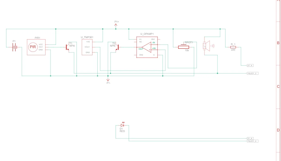
The first problem is your schematic (as well as being mostly unreadable) is incorrect. I don’t believe this circuit will work as specified. The npn transistor collectors connect to ground (they need to be connecting to a positive voltage to work as an emitter follower. It looks to me like the intent here is to turn on the led if either the temperature is above a set point (set by the pot, detected by the lm35) or the PIR triggers with the two transistors providing an (oddly configured) open collector or gate. However as noted this circuit won’t do that as far as I can see. The 741 op amp you used is dual supply (it wants both positive and negative voltages compared to ground. An lm358 (which is 1/2 a lm324 in an 8 pin dip and is available in core parts) would be a better bet as it is single supply, but the circuit still won’t work as configured I don’t think. As to the terminal block, it would presumably connect to a 9V battery t power the circuit (although the series resistor for the led would need to be larger than 220 ohms to limit the current to 10 or 20ma for the LED.) So the first item of business would probably be to find a working schematic. In addition I just noticed that the piezo buzzer will always sound (as it is connected directly to the battery) which seems unlikely to be that which is desired. I would expect it to connect across the LED and only sound when the LED is lit. Once you have a working schematic then we can look at the layout issues (which there are a number of.)
I really appreciate your detailed analysis, thank you so much!
I’m getting really worried now though, someone tried it on a simulation and told me it was working fine, could you please help me with improving the circuit to the desired working (which you understood correctly)
edit: the supply voltage is going to be 5-5.5V not 9V
edit: I’m looking to actually change my design entirely, I’ll make a new post in the “projects” section with an update, really hoping I’d find you there
It is possible that it works. I later thought that the odd use of the transistors may be using the base emitter connection as diodes (why not just use a diode I don’t know though!) That would create the desired open collector output (where either output can drag the output low without damaging the other output as the diode blocks it.) You may still have a problem with a 741 in that circuit, although from the data sheet I see the minimum voltage does appear to be 5V. You are better off with an op amp that is designed for single supply though as the 741 is expecting + and - supplies. I should see posts in projects and will likely respond. That still leaves the buzzer always on which is likely not as intended though.
Been a few years since visiting this Site (I don’t use Fritzing now).
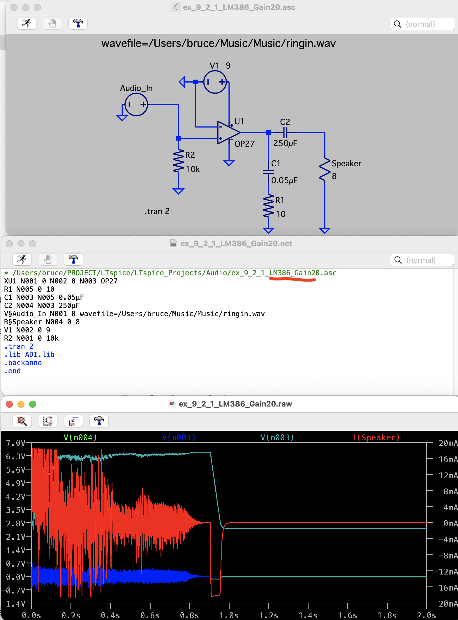
That said, below shows my Audio Simulation (using a Wave file for input signal). Simulation in LTspice using LM386 OpAmp (Text shows it as OP27, never bothered to change the Text)