I’m currently working on the very beginning stages of an auto-dosing project for a hydroponic system. Basically, hooking up the Arduino to three DC Motors and a timing circuit. I’ve never done anything like this, so the going is slow.
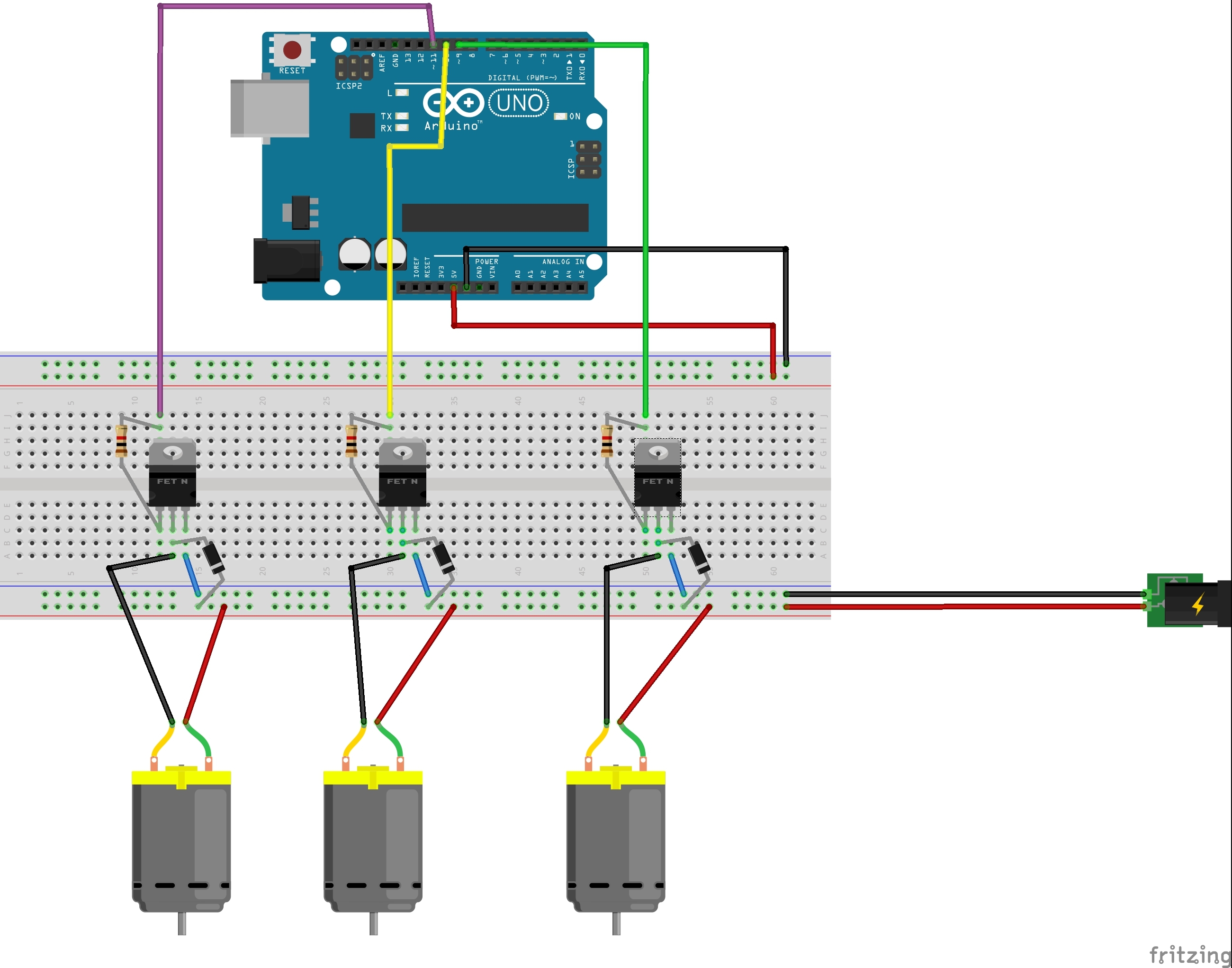
I figured I would start by simply creating the circuit/breadboard to run each of the motors without worrying about the timing circuit. The attached pictures are what I’ve come up with so far (It only allows me to put one image per post, so see the next post for the breadboard image).
Question 1:
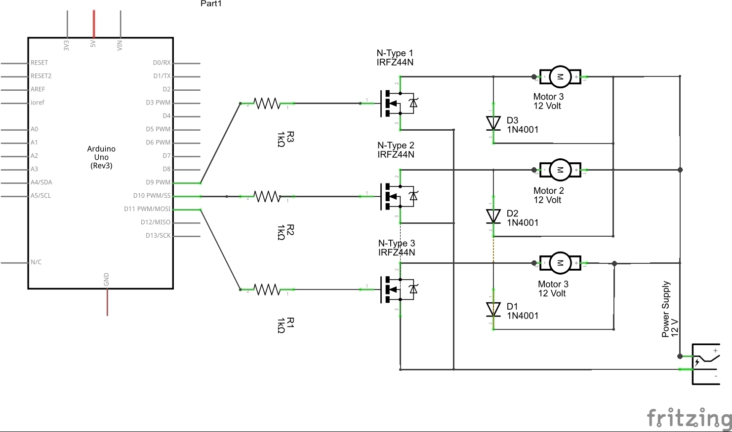
The schematic has a couple “ratsnest” lines that won’t go away (between the 2nd and 1st diodes and the 2nd and 1st transistors)? Does this mean there is something wrong with the way I’ve drawn the circuit or manipulated the breadboard?
Question 2:
On the schematic, I haven’t hooked anything up to the Arduino 5V and the Arduino Gnd like I did on the Breadboard. Is this ok? In other words, is it common practice that these connections are just assumed?
Question 3:
Does this circuit look like it will work (I will only be running 1 motor at a time).
Thanks tremendously in advance, really enjoying this software and learning Arduino.
-Chase