I’ve made my first two attempts at using the software today -
I’m using ChatGPT to build the fzz files for the parts that I need.
I also used it to update the Pi Pico part that I found on a thread on this forum to add labels onto the front.
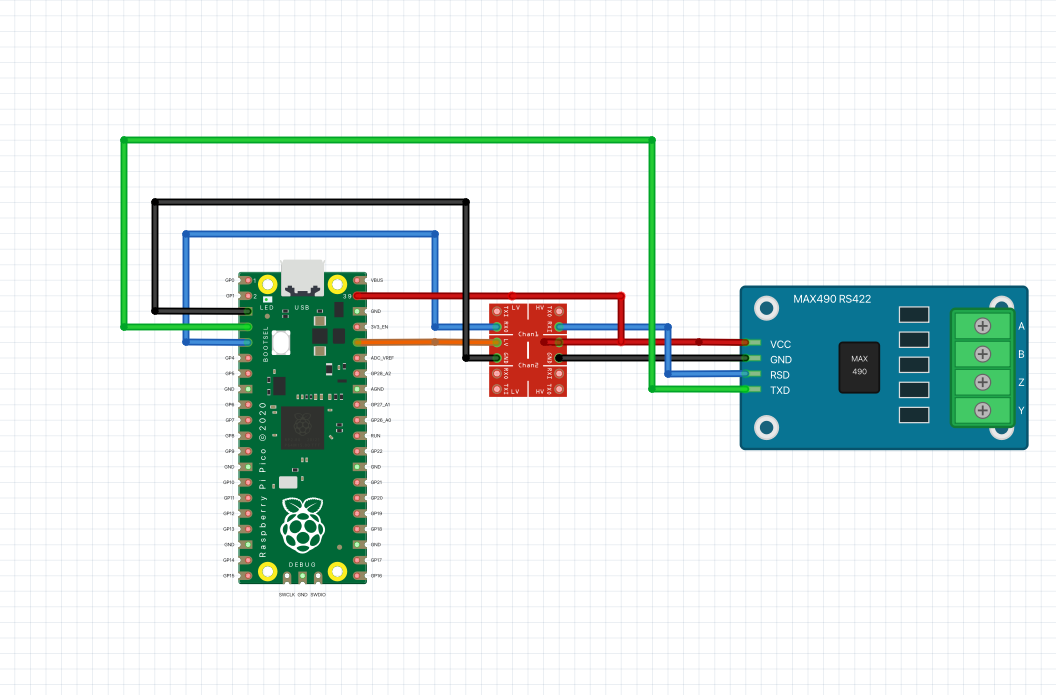
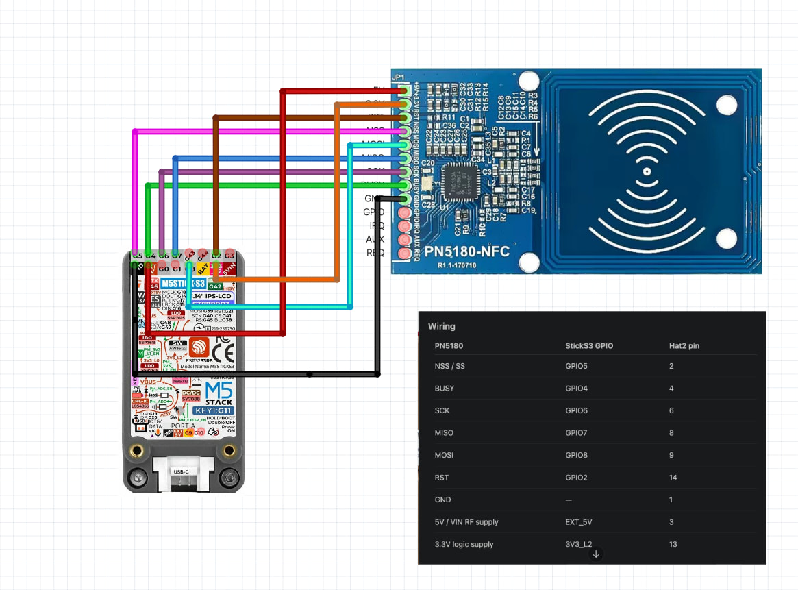
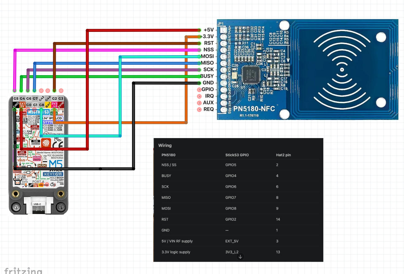
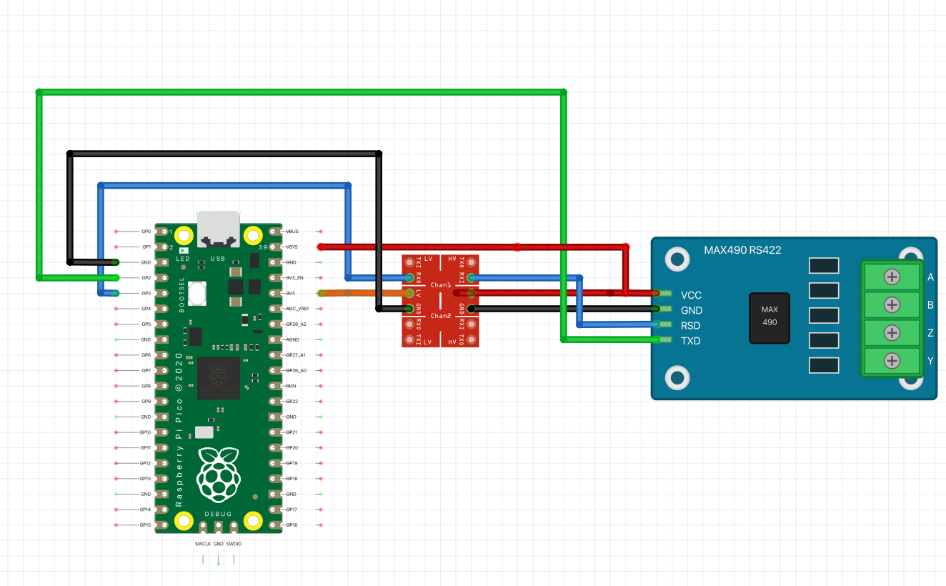
The main issue I am having is that when I place the lines it covers up the labels - is there any way to get the labels to show through the lines - or do I need to somehow offset them in the fzz files? Two example screenshots attached.
If it is technically possible to plug the board into a breadboard, moving the physical pin connection point is not a good idea. Most boards that need direct pin labelling do it on the physical board, ‘inside’ of the pin. That can still get covered when a wire is routed over the board. There is no perfect location for permanent pin labels.
Starting to get the hang of the software - very useful so far.
All parts created either with Claude or ChatGPT,
Also managed to get AI to tidy up the wire routing and check the actual files against designs.
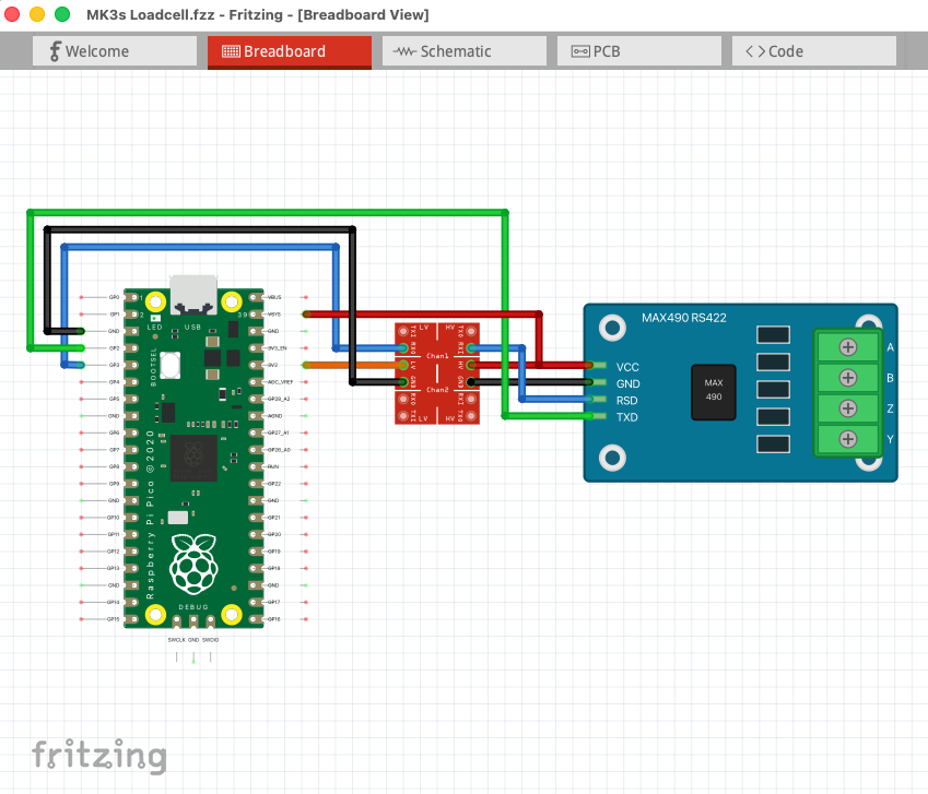
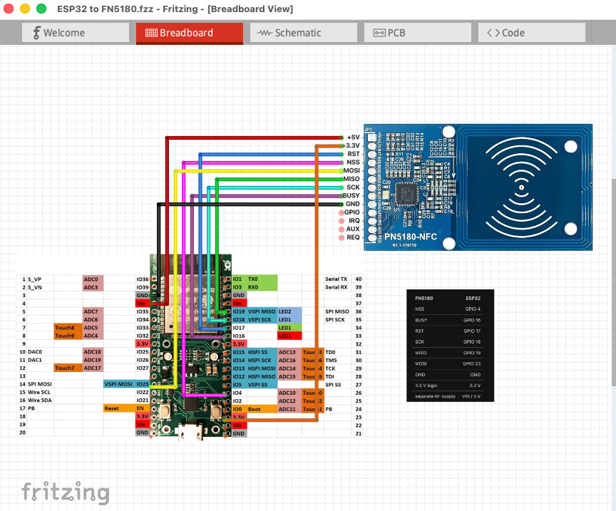

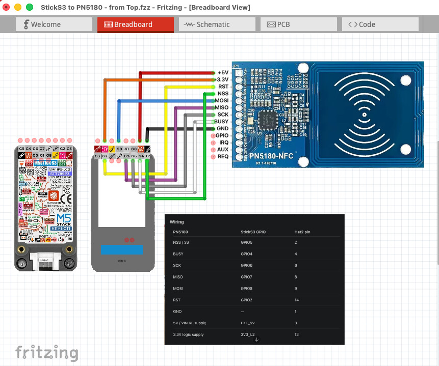
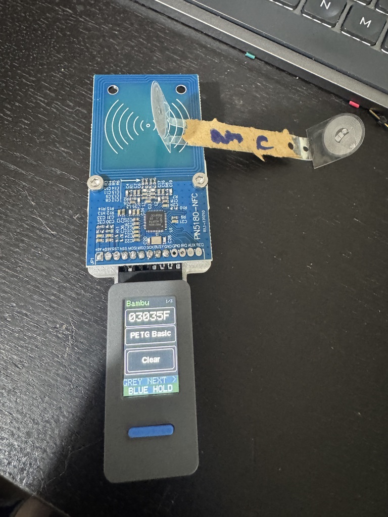
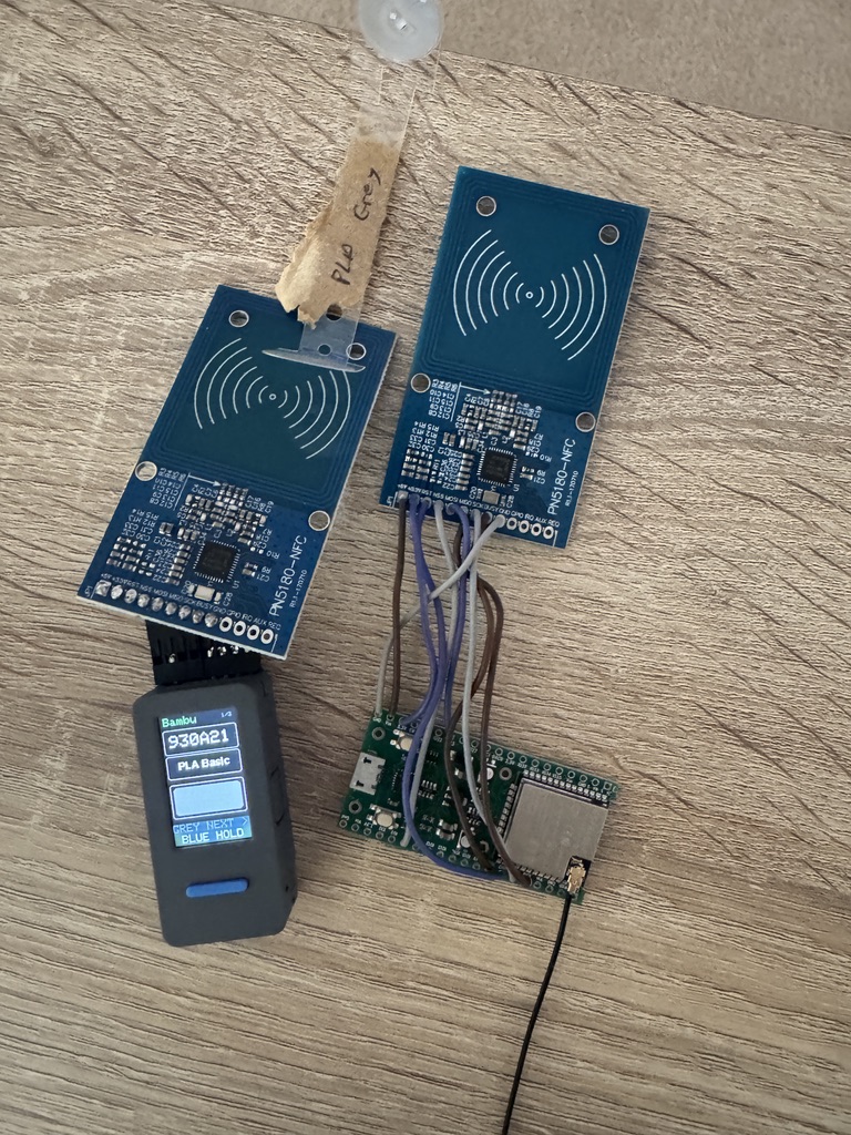
Prior to finding this software I’ve mostly been doing the tracing by hand using the macOS photos app.
The hardest thing I did was trying to get Claude to give me a top view of the M5StickS3 - with all of the connections reversed. I ended up having to tell it what to do in about 15 very specific tiny steps - otherwise it kept changing the image or moving things around.
Worst problem was the pi5 - Claude got the pi5 GPIOs in completely the wrong places - luckily the miss wiring didn’t blow up either board…