Hi,
I need a help with finding a missing parts which are the BMP581 or the BMP580. I am working on my Senior Design and I need them as fast as possible, please.
If there are not existing, can I request someone to do it for me? and how?
Regards
Hi,
I need a help with finding a missing parts which are the BMP581 or the BMP580. I am working on my Senior Design and I need them as fast as possible, please.
If there are not existing, can I request someone to do it for me? and how?
Regards
A google search for “fritzing part BMP581” doesn’t turn up any parts. To make one we would need the physical size and connection information (I assume you are looking for a breakout board rather than just the BMP581 part) such as a web page, although the only examples of breakout boards I see are Sparkfun ones (and they may have Fritzing parts in their repository.) In any case more information is needed.
Peter
Hello,
Thank you for your response.
I am attaching a file that have the information of the BMP581. Have a look at it, please.
For any more information you want please let me know
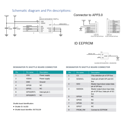
Also, here is the pin information the schematic diagram

This part should do what you want. Of note is there is no pcb view as it doesn’t seem useful, and the pin labels in breadboard and schematic may be in the wrong order (as there is no indication in the documents where pin1 is on the actual board so I made a guess!) It is easy enough to change the pins if the order is incorrect, I just need to know what the correct order is.
edit: Replaced with a part with the connectors aligned correctly.
bmp580-shuttle-board-3_0.fzpz (12.9 KB)
Peter
Hi,
I appreciate your answer.
I am attaching the new and correct order and number of pins regarding to the BMP581 chip. Please, can you fix it for me?
Regards.
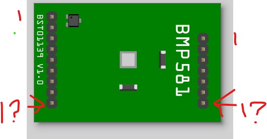
Still not enough information. At present the pins are arranged like this:

]
with pin1 at the top. The question (which is not answered in the data sheet) is where is pin1 in the schematic in relationship to the board at the top as currently set or at the bottom with the numbers with question marks? That will likely only be found by looking at a real board and I don’t have one.
edit:
I found the layout here
which is what this thing plugs in to and indeed the pins are reversed on both connectors. I have corrected the part and will replace the one above with the correct one. You will need to download the part again to get the corrected version.
Peter