I have created a ‘schematic’ on the breadboard tab - I then switch to the PCB tab, but it doesn’t bring all the components across and the files are missing traces?
Any advice please
I have created a ‘schematic’ on the breadboard tab - I then switch to the PCB tab, but it doesn’t bring all the components across and the files are missing traces?
Any advice please
You need to upload the …fzz file for your sketch (upload is 7th icon from the left in the reply menu) so we can see what you are talking about (and see what is wrong) before we could provide any advise.
Peter
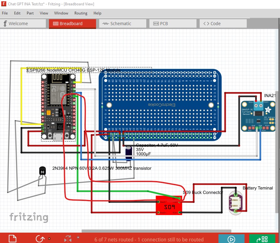
Chat GPT INA Test.fzz (53.5 KB)
Although I still need to make some design changes so as a circuit it may not be correct but when I create the Gerber files it doesn’t translate properly, please help
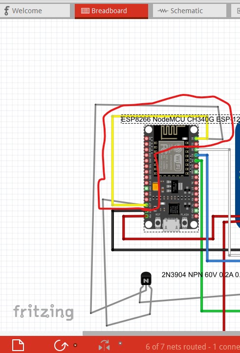
You have a number of errors in breadboard view which will affect pcb view. This breadboard connection is not connected (the connection is red for unconnected when it should be green)
if you right click on a pin that should be connection it will light all connected pins in yellow which it does not for the noted connection.
This connection shorts the transistor base to the emitter which will not work.
This connection won’t work. The power supply enable will likely block the power supply from working making the CPU board never be powered to make the circuit not work. Of these three the first is likely the cause of your problem in pcb though.
Peter
I have addressed the problems (I think) and changed the circuit to go back to basics, but still the Gerber files are not coming across correctly
INA Test Rev1.fzz (53.1 KB)
when I upload to JLCPCB site
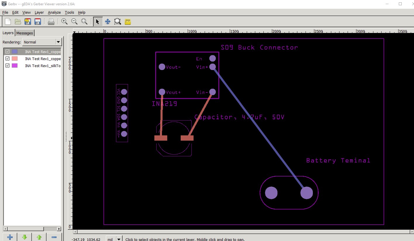
I’m not sure what you are expecting in the gerber output. What you will get is this:
which is the gerber output displayed in gerbv. There are not connections to the CPU board because you haven’t added traces (which wouldn’t work anyway as they truncate at the edge of the board.) If you want connections to the CPU board you would need to move the CPU board on to the pcb and route the connections. If the CPU board is intended to be off the pcb you would need to add connectors on the pcb to make the needed connections (which are not there now.) The only things that will appear in the gerber output are bounded by the grey pcb rectangle anything (such as the CPU board) that is off that won’t show up in the gerber output and traces off board will truncate at the board edge and not connect. I would expect given the Electrocookie breadboard that the CPU board and the power supply should be on the electorcookie board and internally wired (which would make pcb redundant!) If you intend to make a pcb of this, all the parts should be within the grey rectangle (without the electrocookie board) and connected to each other then correctly routed in pcb view.
Peter
Thank you for your help, I think I have solved the problem now by following your advice - thanks