I have designed a shield using the Arduino UNO (Rev 3) part in order to define the pin header spacings so that I can connect the shield PCB to the actual Arduino UNO (Rev 3) sitting below the shield PCB.
The shield circuit model passes the Design Rules Check.
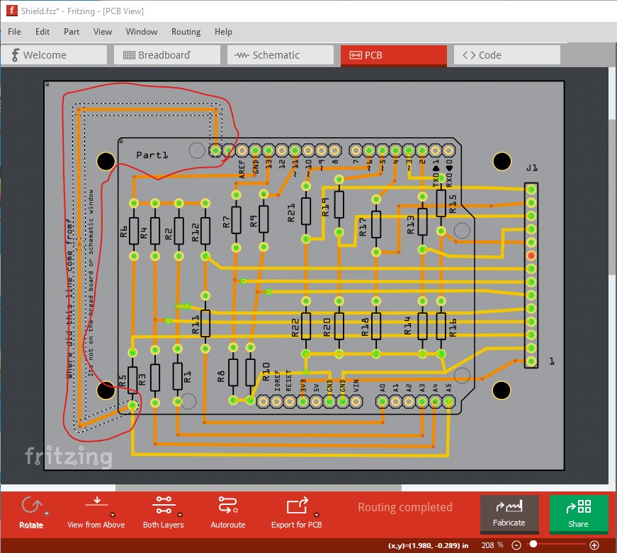
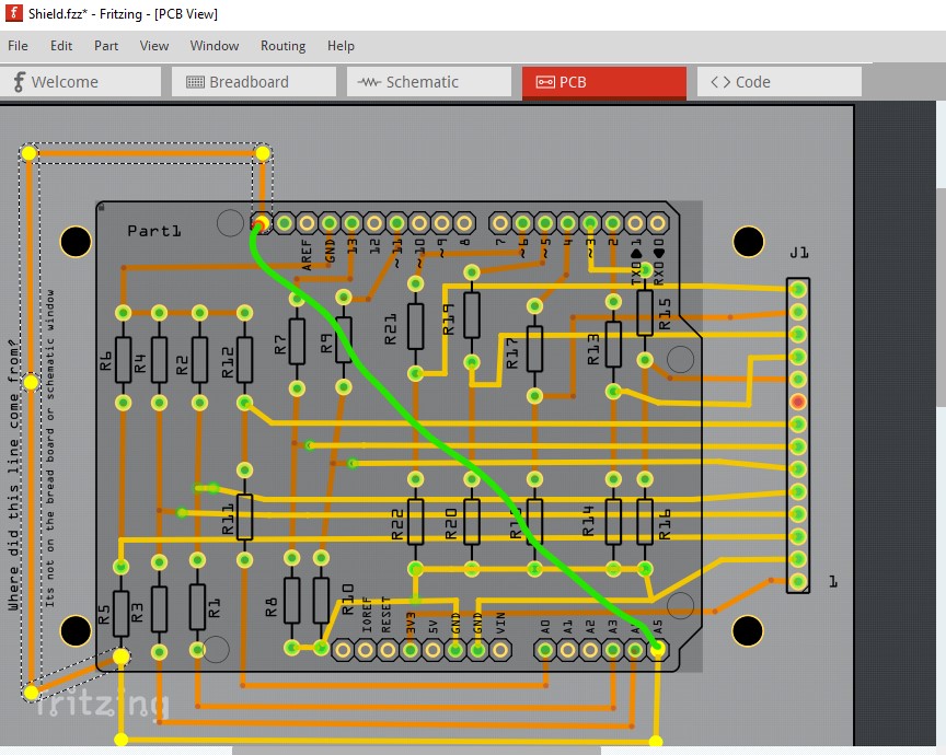
However, in the PCB Window, the Fritzing software automatically placed a wire from the Arduino part Pin A5 up to the Arduino Pin, two pins to the left of Arduino Pin AREF on the top side of the Arduino part.
I did not draw this wire . Fritzing drew the wire. See this wire in the PCB Window of the attached file, “Shield”.
If I take out the wire as done in file, “Shield, No Wire”, then the brown wire from Arduino Pin A5 disappears as shown in the Bread Board and Schematic Windows of this file.
When I connect the brown wire in these two windows, the extra wire reappears in the PCB window.
Is this extra wire, which appears in the file “Shield” PCB Window, required to complete the “Shield” design?
Since the “Shield” file appears to require this extra wire, and passes the DRC check, I assume that Fritzing will prepare the correct Gerber file for the shield PCB build. Is this correct?
Shield.fzz (59.4 KB)
Shield No Wire.fzz (57.5 KB)