Hi all,
I can’t find ESP32 devkit c V4 parts (AZ Delivery ESP32 devkit c V4).
Is there a place where I can search it or anyone that have already created the part?
Thank you in advance
Andrea
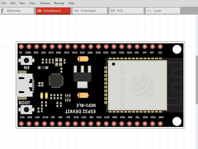
Doesn’t look like there is a part for this exact board but a search for fritzing part ESP32_DevKit_C_V4 turns up this one which may be close enough (it looks to be slightly longer and have a couple of mounting holes the one you want does not have but the pins look the same, don’t know about the width though.)
Peter
Thank you for the hint!
If you need the exact board it is easy enough for me to modify that part to match the board (assuming I can find mechanical information on the board you want, there didn’t appear to be a lot on their web site!)
Peter
Hi peter, sorry for the late reply.
I’ve changed the board that I use for my project.
I switched to the Olimex ESP32 Gateway (Rev. G). (ESP32-GATEWAY - Open Source Hardware Board)
Surprisingly even though they are Fritzing fab partner, I can’t find the fritzing part. Can you help me or point me in the right direction to find it (hopefully) or in the worst case make it?
Thank you in advance
Andrea
There doesn’t appear to be a Fritzing part so it is make a part. Also at Rev E the pin numbers changed. I assume you want a rev F or G board (which look to be the current ones?
Peter
Yes I need the Rev. G which is the current one.
Are you going to make this part? For real? 
Yes, it is almost finished. The 3 svgs are done only the fzp file and testing remains.
Peter
Unbelievable… so fast!
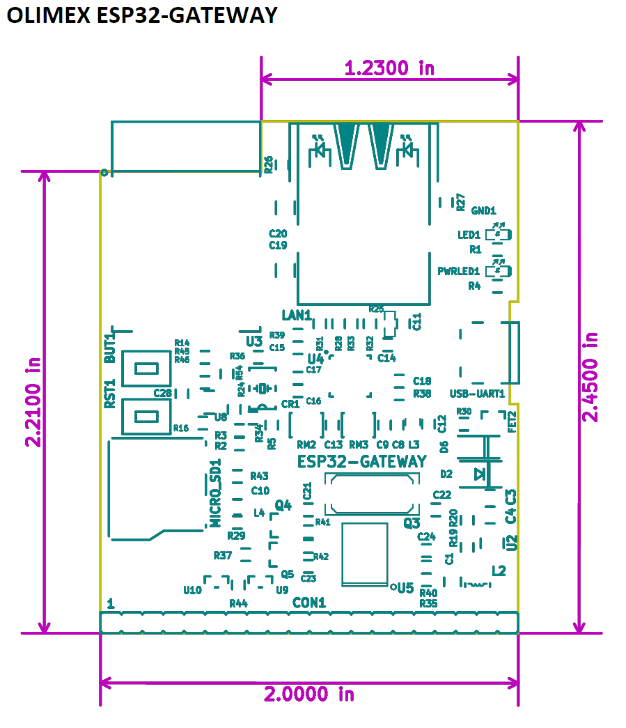
OK here is a part with a few warnings. As far as I can see their board outline (which gives the board dimensions) is old and no longer correct. I made breadboard from the image in the pinout pdf file here:
When I set the base to the sizes in the dimensions file here:
it is too short (2.45 in) so I increased it until it matched the size in the jpg image (2.68in) so checking it against a real board would be a good bet. That also means the mounting holes in pcb (which are as usual only on the silkscreen, if you want holes drilled you need to drag a hole over the hole in silkscreen and adjust the hole to the size you want.) may not be accurate as well (they don’t appear in the dimension drawing anyway) but they are easy enough to change if they turn out to be wrong. Pin labels were set from the Rev F and greater pinout file.
edit: A check against the actual board indicates the part is too high (the dimension page is not wrong.) Found a different image and adjusted breadboard and pcb to the correct (I hope!) sizes and replaced the part, so if you have downloaded this please download this version and replace the original.
olimex-esp32-gateway.fzpz (44.7 KB)
Making parts isn’t all that hard, learning to make parts is (it took me about a year close to full time to learn to make proper parts. ) This took a couple of hours this morning.
Peter
Hi Peter, first of all thank you a lot! I didn’t expect to find someone so reactive.
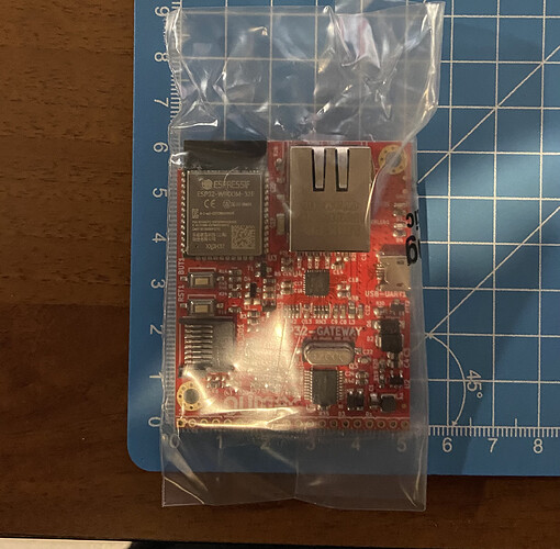
I’ve measured the actual board and it’s ~62mm ( 2.45 in)
Well that is bad news! Could you print out the pcb image of the part at 1:1 scale and tell me where things don’t match? I guess the image in the pdf may have been stretched in Y but not in X (always a danger of doing this with images!) As long as the connector is indeed a .1 in header (which seems likely) the pins will be correct, just the board size and the mounting holes will be wrong. Meanwhile I’ll have another look at the image and see if I can see something I did wrong.
Peter
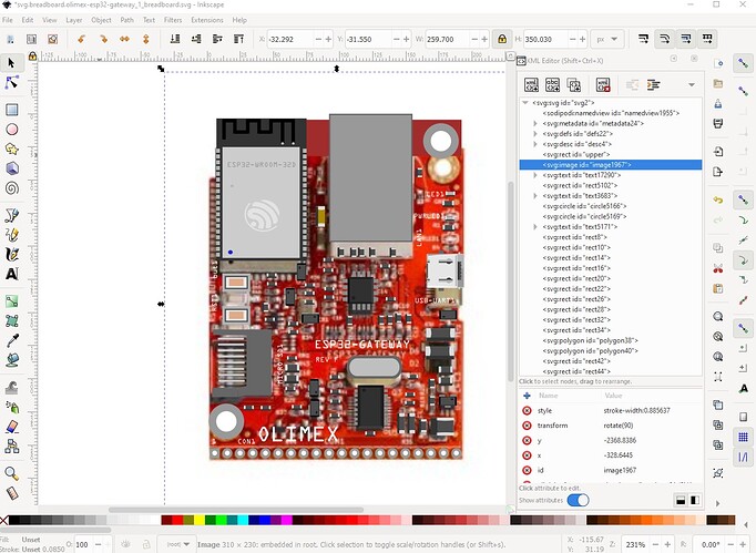
Yes, there is something wrong about the image in the pdf file. I found another jpg on their site and it agrees with your image (and probably the dimensions document, but I havn’t checked that yet.) Here the jpg has been imported in to Inkscape and the board rectangle in the svg moved below the jpg image so the components on the board show up overlayed on the jpg image (to position the parts), indeed stretched in Y. I will adjust breadboard and pcb to the correct dimensions and post a new part.
Peter
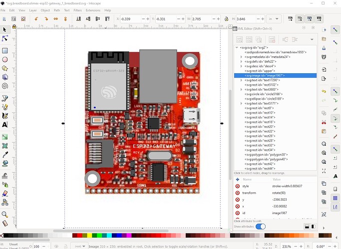
OK I have replaced the original part with a new one that I hope is better. Breadboard is missing the Olimax label and has con1 in the wrong place (because the jpg I used is different again from either the original image or the board) but it isn’t serious enough to redo it yet again. Somehow the image in the pdf was stretched in Y.
This is breadboard with the jpg image superimposed and the parts (but not the connectors!) scaled down to where they should be. When that was done the components more or less line up with the image so hopefully the mounting holes will now line up, if not we can move only them.
Peter
Hi Peter,
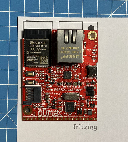
I’ve printed the PCB and checked the “real life” dimensions and imho it’s perfect. The mountig holes line up perfectly.
Thank you for your valuable help!
Andrea
