Name of the part
ESP32-C3-WROOM-02 / ESP32-C3-WROOM-02U
Your previous work, similar parts
I searched for existing ESP32-C3 modules in the Fritzing parts library but did not find a dedicated part for the ESP32-C3-WROOM-02 or ESP32-C3-WROOM-02U module.
There are some ESP32 modules available (like ESP32-WROOM-32), but the pinout and physical layout are different.
Top view
(Insert image here – top view of the module showing pin layout and antenna area)
Example description of the image:
Top view of the ESP32-C3-WROOM-02 module showing the PCB antenna (or u.FL connector in the 02U version), shield, and castellated pins.
Datasheet
https://www.mouser.com/catalog/specsheets/Espressif%20Systems_09072021_ESP32-C3-WROOM-02U-N4.pdf
Footprint
SMD module with castellated pads (18 pins total)
Type
Breakout board, sub assembly, plug in module (A)
Antenna (AE)
Battery (BT)
Capacitor (C)
Diode (D)
Display (DS)
Fuse (F)
Hardware , mounting screws, etc. (H)
Jack, fixed part of a connector pair, header (J)
Relay (K)
Inductor, Coil, Ferrite bead (L)
Loudspeaker, Buzzer (LS)
Motor (M)
Microphone (MK)
Plug, moveable part of a connector pair (P)
Transistor (Q)
Resistor (R)
Thermistor (RT)
Varistor (RV)
Switch (S)
Transformer (T)
Integrated Circuit (IC)
Crystal, Oscillator (Y)
Zener diode (Z)
Other
Hello,
Is there any part in Fritzing with these castellated pads?
I think I’d fail at that.
Regards, Harald!
I found something here. Could this component be adapted to the ESP32-C3?
ESP32-S3-WROOM-1.fzpz (43.9 KB)
Regards, Harald!
Yes, I have that exact datasheet as well.
I’ve already tweaked the file I sent a bit. I think we can handle it.

There are also still 2 pins too many!
I’ll do the other files over the weekend.
Regards, Harald
1 Like
Hello,
Could someone please check the two files?


The dimensions of the PCB view were a bit tricky. The datasheet is further up in the post.
I’ll build the Fritzing part from it tomorrow.
Regards, Harald!
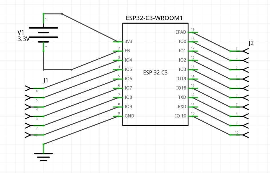
So, as I said, the PCB dimensions differ significantly from the ESP32 component. I’ve attached the PCB view.
For the pads, I tried to implement the specifications from the datasheet.
Here is the component for review and improvement.
ESP32-C3-WROOM.fzpz (18,7 KB)
Regards, Harald!
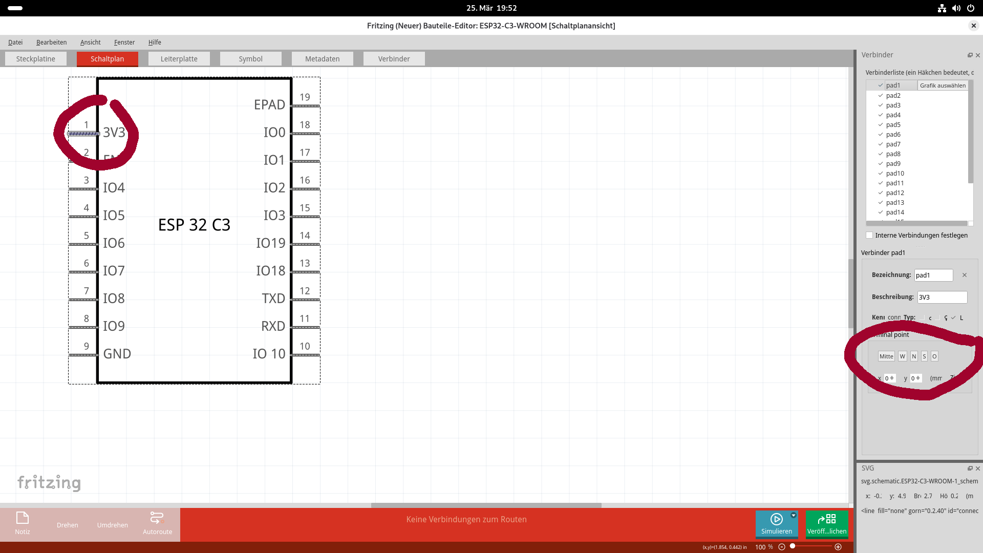
I took a look at the part, it works so far. However, I noticed that the connectors make contact in the middle, not at the end.
Ah, you can actually do that in the editor, I’m not sure if I did it.
If necessary, I’ll have to edit the XML file - whether that will work, I can’t say.
You can try it yourself in the parts editor. The connections need to be set to O (East) and W (West).
Regards, Harald!
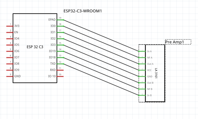
Yes, you’re right. I must have forgotten that. Here is the updated version with the connectors at the end of the PINs.
ESP32-C3-WROOM.fzpz (18.9 KB)
Regards, Harald!
Just checked again, it still looks the same. I then tried to fix it via Inkscape, unfortunately that didn’t work. With my PGA2311, which I published at the beginning of 2025, it worked without any problems. Maybe it’s due to my Inkscape version…
That’s not so nice, could it be that this happens during importing. I changed the alignment of the PINs in the component editor. I went to the component and right-clicked on Edit Component…
Then clicked on each PIN and set the terminal point, either East or West. After that File/Save.
I did not use Inkscape for this.
It worked for me then.
No idea why, but in my last attempts the error was still there. Maybe the file was still in the browser cache, so I kept downloading and importing the first version.
Today it works without any problems…