In addition to @microMerlin 's comments, my first advise is be lazy. Someone else asked for this part a year or so ago and found one (which is broken) that I fixed. It is available here:
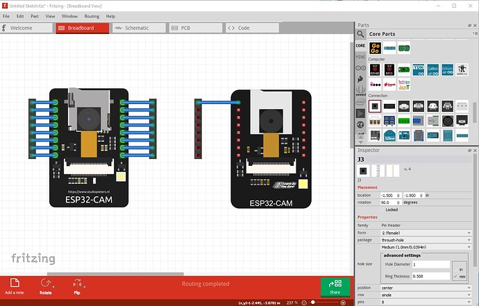
a google search of the form “fritzing part esp-32 cam board” will find it. The fixed part is the left hand part in the following images.
breadboard, pretty much identical
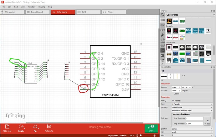
schematic
some problems as noted the lack of terminalId in schematic connects in the center of the pin. The schematic is too large (schematic space is valuable!) and the pins are inverted from breadboard (which isn’t an error necessarily as they connect correctly, but is confusing.)
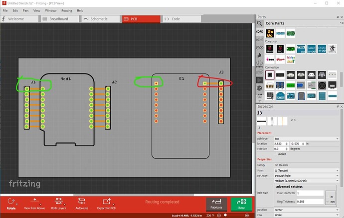
pcb has the main problem, the alignment is incorrect. It should be the same as breadboard but is inverted (you would need to mount the camera on the bottom of the board for the pins to maybe be correct!) The pin circled in red should be on the other side of the board (circled in green.)
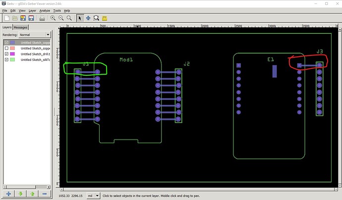
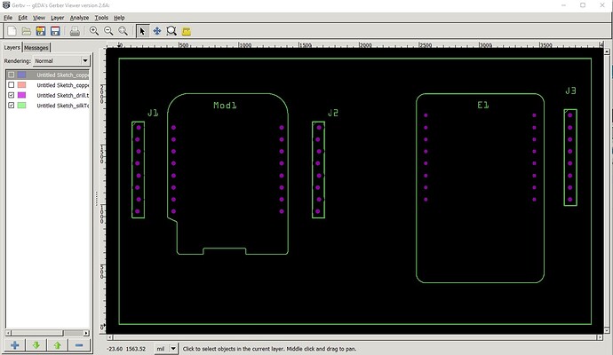
In the gerber output the same thing applies the pin should be on the other side of the board.
Despite what FritzingCheckPart reported all the drill holes are present (although they appear to be too small for 0.1in pins
Peter
