Hello,
I am creating my own part unfortunately encountering the error likes attached screenshot. Anyone have the same issue? FYI, I am using the paid version of Fritzing 1.0.2.
Thank you very much.
Tuan
Hello,
I am creating my own part unfortunately encountering the error likes attached screenshot. Anyone have the same issue? FYI, I am using the paid version of Fritzing 1.0.2.
Thank you very much.
Tuan
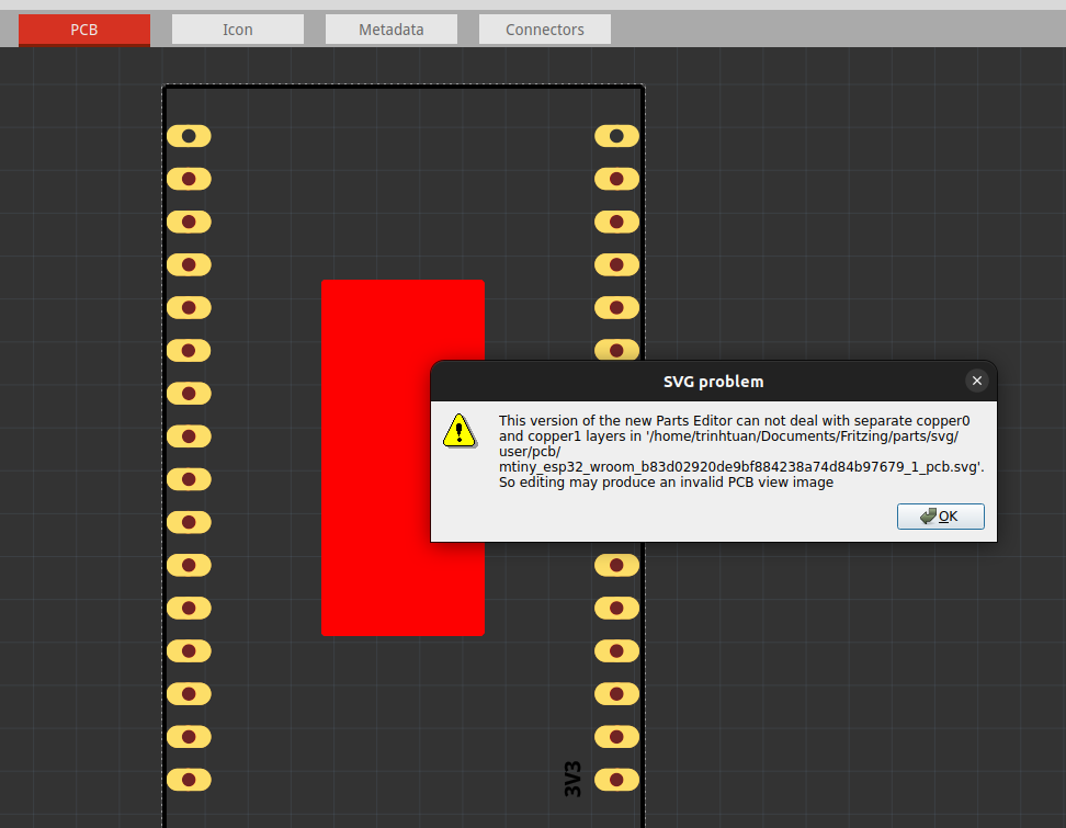
The red rectangle indicates the connectors are not correctly defined. If you upload the .fzpz file for the part involved I will tell you what is wrong with it (upload is 7th icon from the left in the reply menu.)
Peter
The message is about separate copper0 and copper1 not being supported by the parts editor. Fritzing can handle that, but parts editor needs one grouped inside the other in the svg file.
Hi @vanepp ,
I managed to fix the error yesterday by reading the xml (.svg) and re-arranging layers’ order in Inkscape.
However, by that test & learn, I found a bug in Fritzing 1.0.2. Following steps are for reproducing the bug:
I believe if we export from Fritzing then we should be able to reuse without any issues. What do you think?
Thank you,
Tuan
Depends on what the source file is. If it is in the old separate coppero copper1 format Parts editor won’t load it (but svg export will export it probably correctly.) The parts editor was not completed when development stopped int 2016 and so far the developers have not completed it (I believe it is in progress) so the limitations are still present. Some of the parts in core parts are still in the old file format with separate copper1 and copper0 as no one has updated them. If you provide which part you are exporting the svg from I’ll have a look at it.
Peter
Nope, SGV export function does not work correctly as I reported above. It exports .svg with two separate copper0/copper1 layers even the part’s .svg was design correctly (using InkScape) i.e.
<copper1><copper0></copper0></copper1>
Thanks,
Tuan
If you have an example it should be reported as a bug. The exporters should not be exporting in the old format AFAIK. It may be that there is a bug being tickled that exports in the wrong format (the old format is still supported for old parts that haven’t been converted) but the developers would need an example case that does such an export in the wrong format to fix it.
edit:
If you upload the svg that you used (upload is 7th icon from the left in the reply menu) along with the steps you took to import and export the svg from Fritzing I’ll see if I can reproduce and report the issue.
Peter