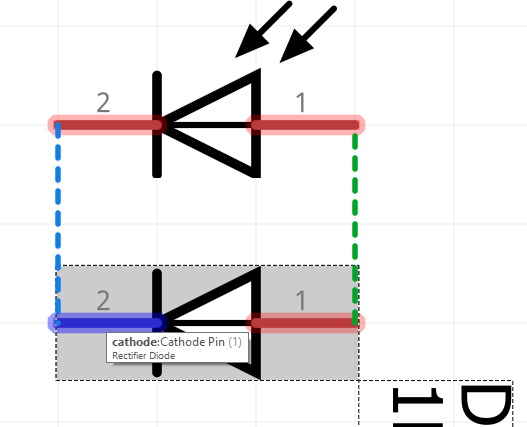
Used the part as defined in my schematic and PCB layout. The schematic shows the diode symbol reversed with respect to the naming of the pins. The naming of the pins is consistent in the PCB view. The silkscreen is correct in the layout (cathode marked with a circle). The pad selection is also consistent with the pin naming, circular pad being the cathode and the square pad being the anode.
What I expected should have happened instead:
Diode symbol should be flipped in the schematic view to be consistent with the layout and pin names.
My version of Fritzing and my operating system:
Version 0.9.3 (b5c895d327c44a3114e5fcc9d8260daf0cbb52806 2016-04-19) 64 [Qt 5.6.1]
Windows 10
It may come sooner than you think. El-j has been pretty good about processing the pull requests for parts as long as the pull request is correct (which I expect this one will be).
There is a problem with that one in that the silk in PCB is white, and that makes it hard to identify in the icons in Insp when you hover over the part. I usually click on the silkscreen group in the XML dialogue of INK and hold shift and click on the blackest square on the bottom colour toolbar.
Sorry if I’m a bit picky.
What the distance been pins supposed to be because I’m getting 180mil.
It’s the convention to put the sq pad next to the marker.
The parts check script will correct this as it checks the part (one of several modifications it does make to the svgs), but it looks to be done already in @sublimeartistry 's part.
Me too! This part has a few more problems: missing terminal Id definitions in schematic for one (which results in wires connecting to the middle of the pin in schematic). The svgs are scaled wrong too. If we are going to update this in core I’d rather see the update done entirely correctly so it doesn’t have to be redo later … We should find the data sheet and verify the entire part in my opinion before doing an update to core.
This is a result of using the parts editor. It doesn’t care what color you use it changes them for you. I think it was an attempt to make things more consistent.
This again is a result of how the editor does things. I would also think it is a sign of how they would like parts made as it was the direction they were going. If they are trying to make a new Web tech version of Fritzing with a parts editor being first thing I would think it would be similar to the current one. It would be safe to say all of this information is in the the API docs.
So far I just switched connector pin / terminal in schematic view and pushed to github repository so the part still working without any rescale / color changes on pcb in order to keep it simple.
My fault, I was looking at the svg after I had run it through the script. The one posted is indeed white in silk when I re unpacked it.
Sounds like the upload without that is already done …
I don’t agree and the parts format document is ambiguous:
“The terminalId attribute is optional. Each connector takes up a certain area in a part (in the example above, it’s a rectangle), but a wire will actually attach to a connector at a single point within the connector’s area. This point of attachment is called a terminal point. The default terminal point is the center of the connector area. If you want the terminal point elsewhere, the terminalId attribute points to yet another element in the SVG file. Here is the SVG element for the terminalId attribute “connector0terminal” in breadboard view:”
TerminalId is indeed optional, as it says, if you omit it, then the wire connects to the center of the pin. In breadboard that is often fine as the pin is square and the center is where the connection should be. In schematic I think it is less fine as the pin is usually .1in long by 10 thou wide which means the wire will connect .05 in from the end of the pin which to me looks ugly. The n/s/e/w setting for terminal in parts editor will set this correctly and sets the terminalId so I think it can be argued either way. Most (but certainly not all, although I think that is an oversight rather than intention) of the parts in core have terminalId in schematic at the appropriate end of the pin. My script warns (but doesn’t error because it is optional) if that is not the case. I’d like to see us come to a consensus of what we would like to see (and I’d like to see terminal on the end of the pin as is possible now) and lobby and/or help make that true of the new design if it proceeds.
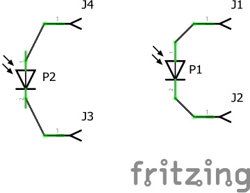
In fact in this case there seems to be an error in your uploaded part. For this the diode on the right (p1) is the one from core and the one on the left (p2) is your new part. The original is what I would say is correct in schematic. Yours lacks the terminalIds (which the original obviously has although I didn’t check the svg). As well your pins appear to be offset from the .1in grid by .05in. That should mean the part submitted to github should have schematic correct, but not the scale nor silkscreen being black but neither of those are vital.
That would be my fault for not setting them to the ends. Just because I don’t usually edit schematics and I simply did what I do for PCB images. I would agree that having them at the ends is nicer and has been an issue on a few things I made in the past like Nixie tube schematics which did not exist in Fritzing.
The silkscreen color would have been updated to black if I had exported the SVG and reimported it but since I only changed the pins it stayed white.