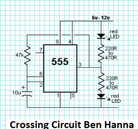
Found a flashing light schematic on facebook. Not able to gt it too work. Found Fritzing and attempting to create Schematic in this program. Can get the LED’s to light up using the 555 timer, not blinking. What do I need or am I missing in this project?
There is so much wrong here I just started from scratch.
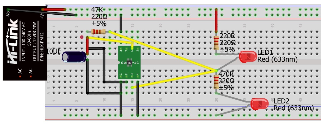
First the power supply part looks to have a problem as it causes routing errors. So I started with a blank sketch and used the parts search to search for 555, picked the dip 8 version (which is probably what you actually have) and dragged it in to schematic view. Then I searched for battery and dragged the 9V battery in to schematic. Then a capacitor and used inspector (lower right window) to change the value to 10uf. Then a resistor and again used inspector to change the value to 47k. Then two more resistors left at the default 220 ohms. Then two leds. Which completes the parts. Now in schematic and breadboard views drag the parts til they match this sketch:
now switch to breadboard view and look at the lines that
connect the resistors and the leds and the 47k resistor and the capacitor. If yours don’t match the sketch then select that resistor and right click and select rotate 180 degrees til they do match. It is important that the alignment in schematic match that in breadboard. Now connect the rest of the wires in schematic giving sketch
Thank You Peter. I learned a lot about how the Fritzing program works. Did not know how to change the values for a given component in inspector. I have a hard time comprehending written instructions. Very grateful how you stepped through the process! Was over complicating this wonderful program. Being color blind is a rather difficult handicap when it comes to any wiring I have had to do. Found an app for my phone the other day that has aided in my circuitry endeavors, was written for the blind.
The important things to remember in Fritzing are that the three views are linked, so changes in one will automatically appear in the others and the direction of components matters (because every pin has an internal identifier) so orientation between views matters that is why the bb_align.fzz, a common problem is to get the resistors or leds in breadboard opposite to those in schematic. When that happens the components get shorted together and routing becomes a mess. As well the top 2 and bottom 2 rows of the breadboard connect horizontally and the 5 pins on either side of the center line connect together vertically (as I recall some of your components in the original were shorted by being connected to the same set of 5 pins). The top and bottom horizontal strips don’t connect to each other by default, so your original would have needed a wire from the ground on the top to the ground on the bottom to work. If you run in to problems feel free to post, there are lots of useful tricks various of us know (and a number of bugs too unfortunatly.)
Also a legacy ratsnest(dotted) line might be left behind when you change a part in a view due to the other views thing it should still be connected, so check if it still needs to be there in all views and delete if necessary.
A connection highlights a pin, so they should look different, and you can click on a pin and every connected pin will highlight to show you what else is connected to that.
 Not able to gt it too work. Found Fritzing and attempting to create Schematic in this program. Can get the LED’s to light up using the 555 timer, not blinking. What do I need or am I missing in this project?