Electrosmith Daisy Patch Submodule

Please help me make a Fritzing Object for this board, please.

Name of the part
Electrosmith Daisy Patch Submodule

Datasheet
The official documentation of the part manufacture is linked here: https://daisy.nyc3.cdn.digitaloceanspaces.com/products/patch-sm/ES_Patch_SM_datasheet_v1.0.5.pdf

Type
I did not read this
[?] Breakout board, sub assembly, plug in module (A)
Antenna (AE)
Battery (BT)
Capacitor (C)
Diode (D)
Display (DS)
Fuse (F)
Hardware , mounting screws, etc. (H)
Jack, fixed part of a connector pair, header (J)
Relay (K)
Inductor, Coil, Ferrite bead (L)
Loudspeaker, Buzzer (LS)
Motor (M)
Microphone (MK)
Plug, moveable part of a connector pair (P)
Transistor (Q)
Resistor (R)
Thermistor (RT)
Varistor (RV)
Switch (S)
Transformer (T)
Integrated Circuit (IC)
Crystal, Oscillator (Y)
Zender diode (Z)
Other (Development Board)

This part should do what you want. Pcb view is suppressed as not useful.

Electrosmith-Daisy-Patch-Submodule.fzpz (20.7 KB)

Peter

2 Likes

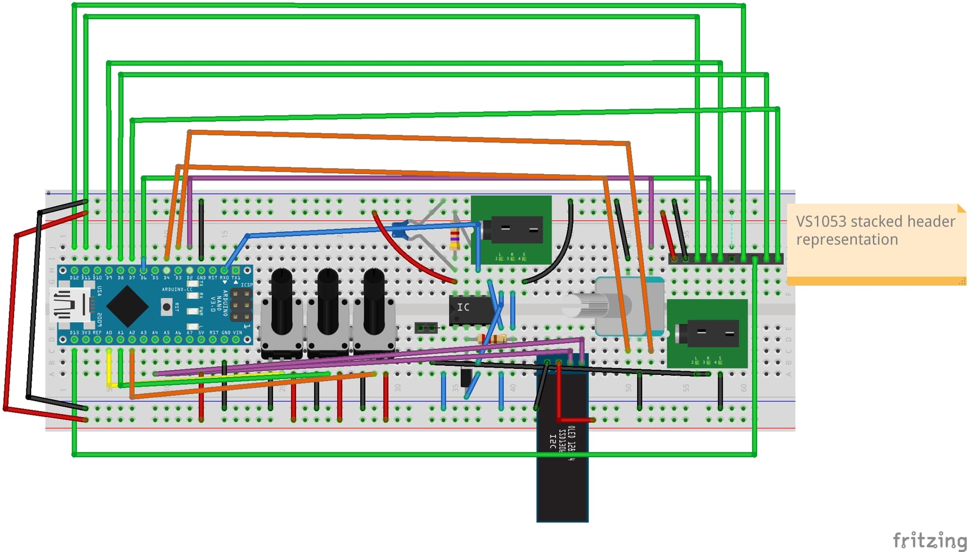
I agree that a pcb view of the Patch is not useful but maybe of the Daisy board? I have to do a number of small parts and still don’t have the confidence, but I have been using fritzing to produce PCBs for years. The footprints for the arduino nano and the Pi Pico I’ve used on two designs and it’s really nice to have them on PCBs. Or maybe the Daisy is ‘too niche’? I do mostly audio with Fritzing.

I expect this is too niche. If someone wants a Daisy board I expect they will request one.

Peter

Heh. I never expected anyone to request a Daisy Patch :slight_smile: Thanks for all your efforts!

Thanks so much for this part @vanepp@poetaster did you ever get PCB footprints for this working?

1 Like

I haven’t tried it yet since I just used pin headers. I also only have one daisy and use pico2 raspis for most things (the olmex versions with 8 ADC broken out).

Just a note on that pico2 vs. daisy. Even ‘just’ pwm (at 48khz) on the pico2 is really good quality. And I can’t justify the margin on the daisy when I can get pico2 xl versions for 5 euro. I also have a project or two with i2s audio out and even then with an extra chip it’s still 10 euro in comparison with 35+ euros.

I just recently did a design ( GitHub - poetaster/trebuchet: trebuchet is an arduino/lgt based synth that primarily plays swinging euclidean transforms on midi drums using the vsi VS1053b. Oh and midi synth. Oh, and sample mangler. ) which has a similar issue with headers where you have two rows (5 in this case) and it’s difficult to use that in the bread board view. I did have the part in the sketch for reference, but the ‘real’ parts on breadboard and pcb are just header pins.

Here, the stacked 2 by 5 just in a row.

and on the pcb as it is on the module

1 Like

Are you using the header on the PCB manually there @poetaster? I had a crack at converting this Patch Submodule KiCad footprint to Fritzing…

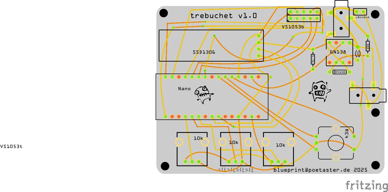
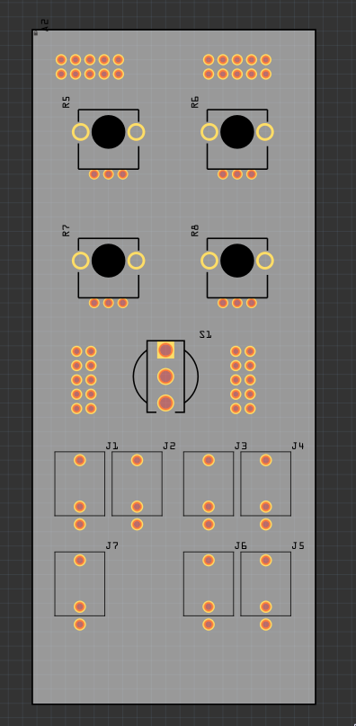
It appears from the image (which is a bad thing to try and estimate hole size from!) that the pads are too large and shorting each other. You would be better to us a 5 pin header (which has correct pads) to either correct the size of your pads in your svg or replace them entirely. You also need the correct pcb groups (copper1/copper0 for through hole along with the correct connector designations) to make it actually work in Frizting. If the copper is overlapping as it appears then the pads will all be shorted together (which should show up in both breadboard and schematic as additional rats nest lines between the connectors.)

edit:

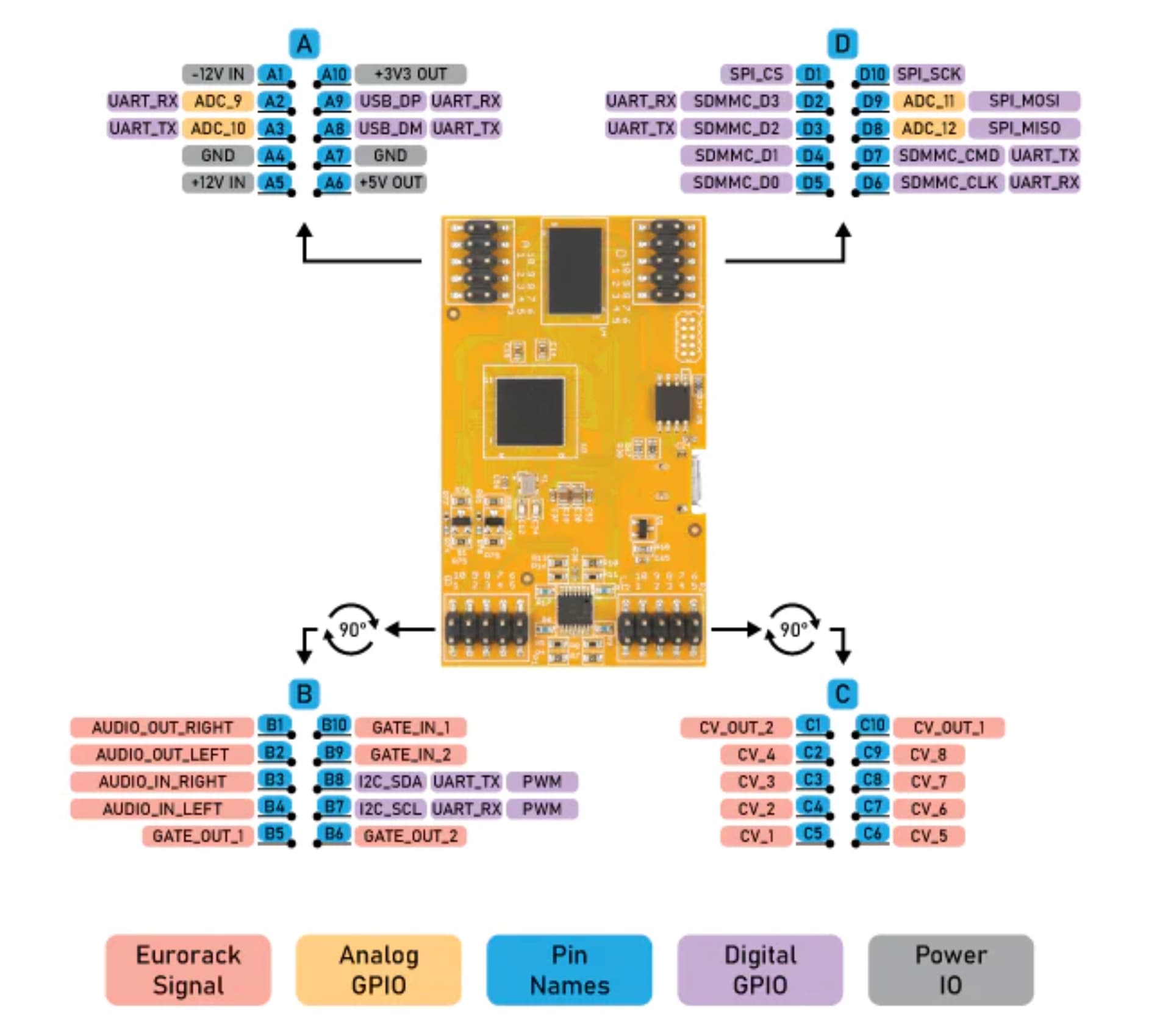
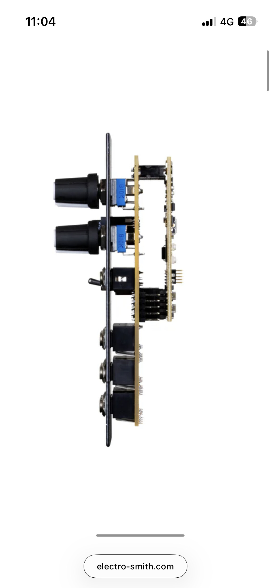
If you are looking for a pcb footprint for the above module (I didn’t immediately see that you are trying to add pcb to the current part) I can easily enough add that. I did not because I don’t see a lot of use for it since the actual module has headers installed and thus won’t fix on a pcb and I didn’t see any point to doing the work involved.

Peter

Thank you @vanepp, the correct PCB view would be great. For better or worse they are meant to be attached to a carrier board like:

This part may do what you want. The may is caused by the layout being made from the pdf file for the board and the pcb footprint will only be as accurate as the pdf file is. Print out the pcb file at 1:1 scale (the default) and try it against a real board to see how well they match. I suspect if it is only a little misaligned it may work fine, but I am not sure how accurate it is.

Electrosmith-Daisy-Patch-Submodule-with-pcb.fzpz (22.2 KB)

Peter

That aligns nearly identically to the KiCad file I converted, with proper contacts. I’ll check the irl alignment. Thanks @vanepp

1 Like