I don’t know of a way to do this. The conversion is picking up “connections” which in Eagle is also ICs and other internal parts where Fritzing only wants the connectors (not the ICs or passive components.) There isn’t currently a way to do this that I know of in Eagle2Fritizing so you have to manually delete the connectors for ICs and passive components (as well as add breadboard view images for the parts that aren’t in the “and” file which I usually do manually as well rather than update the “and” file) but that is still a lot easier than making the part from scratch. There is also a lot of editing required in the fzp file as well since Fritzing prefers that the pin numbers be in order and eagle2fritzing usually leaves them out of order because of the extra connectors being deleted. I have some python scripts that will help with that by rearranging pin numbers in svgs but they are still too crude for general release yet as I have to modify the python code to change the behavior to match the what the current file needs. I haven’t yet figured out how to do that from the command line yet
edit: For schematic I usually ignore the eagle2fritzing schematic and create a new one from either the templates here:
or lately via Randy’s Inkscape extension here:
because the eagle2fritzing schematic is the wrong scale, wrong colors and has pins which are the old style .2in long rather than the current .1in long (which both of the above use!)
Thank You for valuable support and the information.
may I ask, Is there any other PCB design tool that can convert in to svg file format or
Is it possible to convert a PCB design file directly to a fritzing file?
Not that I know of. The eagle2fritzing program was made to help convert the all the Sparkfun Eagle files in to Fritinzg parts. I’m not aware of any other format that is supported.
hello,
i have one project which is done by my self with the help of you and few documents and i want somebody to check the files i have created is correct or not.
can you please suggest or help on this?
i have fzpz/ svgs&fzp files.
Upload the .fzpz file (it contains the fzp an all the svgs) and one or more of us will have a look and suggest fixes if needed. Upload is 7th icon from the left on the reply menu.
OK, first let me say that the only three changes you really need to make in your part are to correct the ground bus below, add the terminalIds in schematic and correct the breadboard layerId. The rest of the changes I made here improve the part but do not make it more functional. I’m retired, so my time is my own and I can make good parts without worrying about how long it takes. I expect the same isn’t true for you so maybe just the bus change, breadboard layerId and schematic terminalId are all you want to do of the changes below. The first thing I did is run the part through FritizngCheckPart.py to see what errors it finds (I suppressed the less important ones here):
Warning 11: File
‘part.BLDCMotorControlShield_a2e2d14f75d5e12c0a44cdd42b393f22_28.fzp.bak’
At line 50
Type female is not male (it usually should be)
Error 53: File
‘part.BLDCMotorControlShield_a2e2d14f75d5e12c0a44cdd42b393f22_28.fzp.bak’
At line 383
Bus nodeMember connector279 does’t exist
Error 69: File
‘svg.breadboard.BLDCMotorControlShield_a2e2d14f75d5e12c0a44cdd42b393f22_28_breadboard.svg.bak’
At line 18
Found a drawing element before a layerId (or no layerId)
Warning 14: File
‘part.BLDCMotorControlShield_a2e2d14f75d5e12c0a44cdd42b393f22_28.fzp.bak’
At line 297
terminalId missing in schematicView (likely an error)
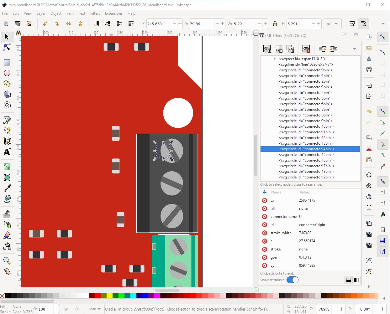
The type female complaint is a warning not an error. Any of male, female or pad are valid (I don’t know what pad does though!) If set female as they are here, they won’t connect to the breadboard and won’t have the red/green color on the connector when connected. Since you don’t care about connecting to the breadboard or not I don’t think, I changed them to male so connections are indicated by color change. The bus node member error is because the connectors specified in the bus connection are not active connectors. The 4 ground connections (connectors 0,4,5 and 21) need to be added to the ground bus and the 5V bus deleted as it is not used. If the ground pins are not bused together the single ground connection in schematic will not work correctly. The drawing element before a layerId or no layerId error (no layerId in this case) is because the fzp file specifies the breadboard layerId as breadboardbreadboard but the svg is set to breadboard. The breadboardbreadboard layerId is special and will make the part be able to move under the breadboard in breadboard view (which parts can’t normally do.) Since I don’t think you want or need that, I changed it to breadboard to make it a standard part. The layerId not matching will cause Fritizing to not export your part as part of an exported image file (svg, jpg, png etc.) which is why this is an error. Now a breakdown of my changes by file. First the breadboard svg:
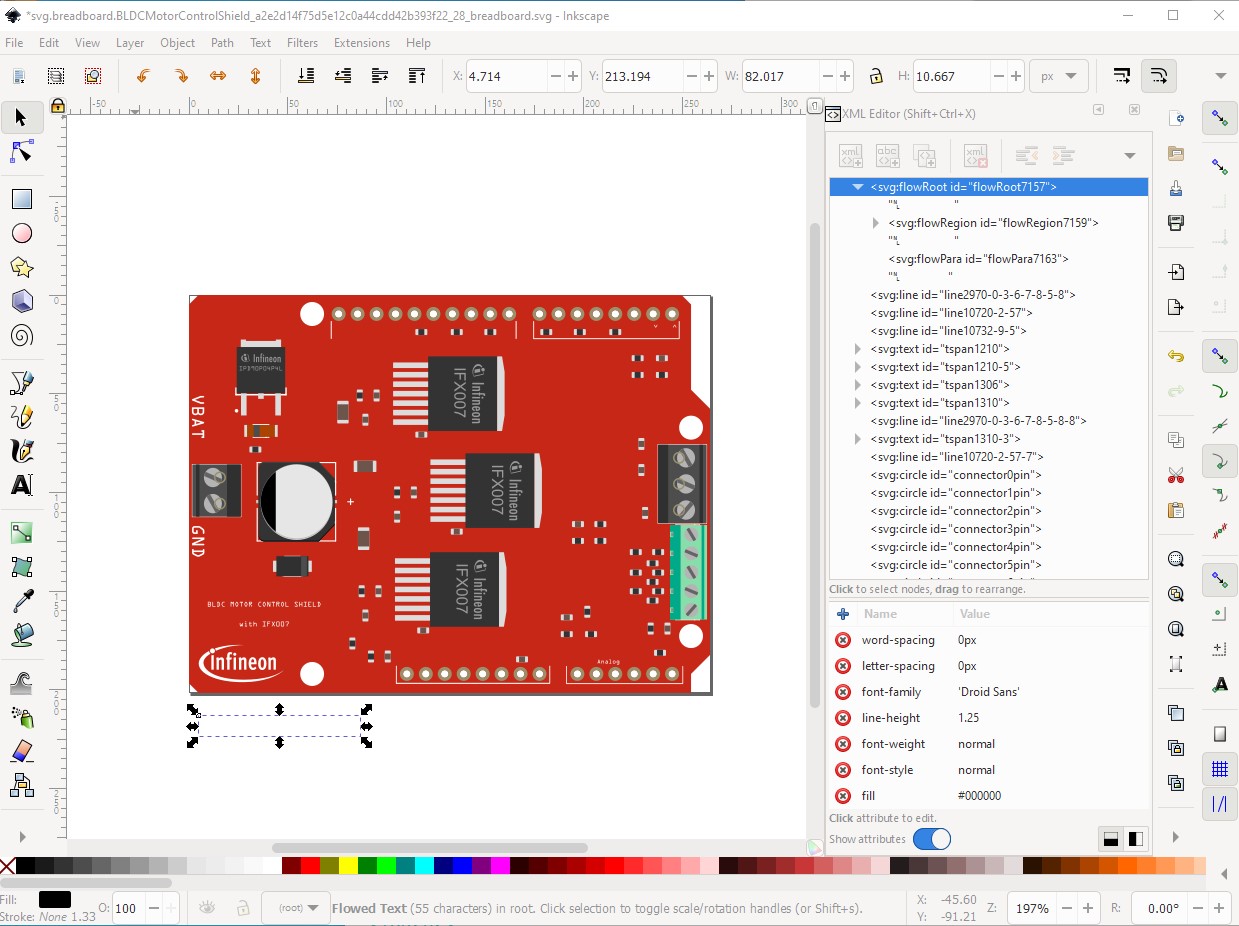
Edit the file in Inkscape and ungroup it entirely. Then remove the flowroot construct. I doubt Fritzing will support it and it is increasing the size of the view box which is undesirable.
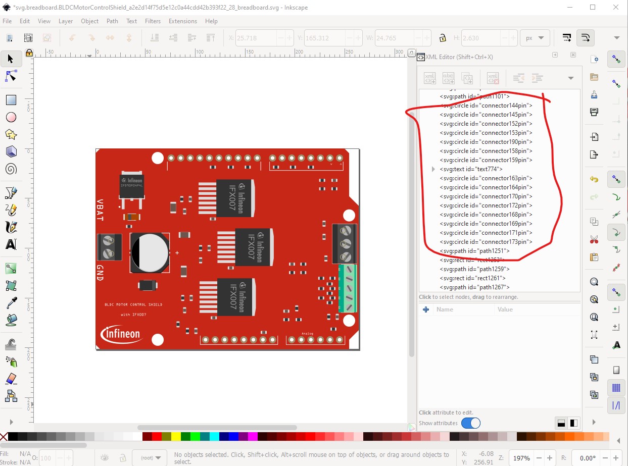
then move the active connectors (0-21) to the bottom of the svg. This isn’t required, but makes changes easier with a script. Now with a text editor on the svg file change all the unused connectors by deleting the trailing “pin” then replacing “connector” with circle so the only things with an id of connector are active connectors. Not required but more readable.
also not required but desirable, rescale the svg to meet the graphics standard specification of drawing units being in 1000 of an inch. Edit->select all, Edit->resize page to selection, object->group and name the resulting group “breadboard” and save as plain svg and breadboard is done.
On to the pcb svg:
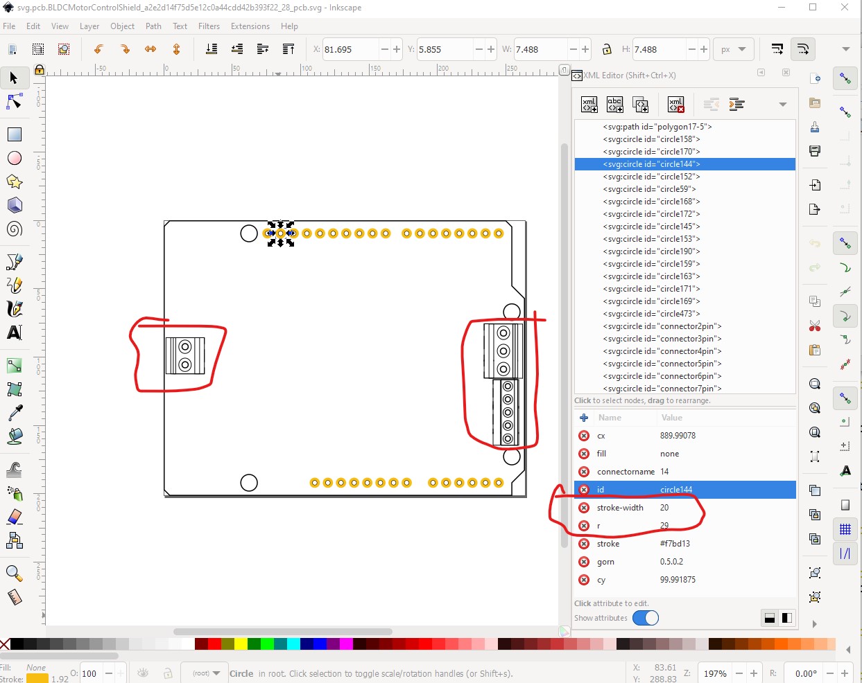
Ungroup, then remove the connectors for the terminal blocks (which typically don’t appear in pcb) then move the active pins to the bottom of the svg as with breadboard for the same reason. Then do the optional rescale of the svg. That tells me the pads are not the correct size. Typically for .1 headers we want the hole to be 0.038in which translates to (at this scale) a radius of 29 (currently 28.499958) with a stroke width of 20 (to give a 20 thou ring around the hole) currently 17. In Inkscape the size of the drilled hole is calculated by
hole size = pad diameter - (2 * stroke-width)
the radius of 29 creates a 0.078in diameter pad which gives the desired 0.038 hole (which can be verified by checking the hole size in the gerber drill.txt output file.) In this case I used a text editor to change all the stroke-widths to 20 and the radius to 29. For the pads that are not active connectors, I removed the the trailing pad and replaced “connector” with “circle”, so those pads will appear on the copper and get drilled at 0.038 but aren’t listed as connectors in Fritzing as they aren’t used or defined.
Here the screw terminals no longer have a pad on the pcb (as it won’t connect) but the unused pins have a pad and will be drilled with a 0.038in hole (because of the radius 29 and stroke-width 20) without being listed as a connector and the active connectors have their connector number attached as their ID so Fritzing will find them. We need to make some changes in the fzp file for this to work (at present Fritzing will complain about the lack of connectors in pcb for the screw terminals!) Then regroup the svg and save it and pcb is done. On to schematic.
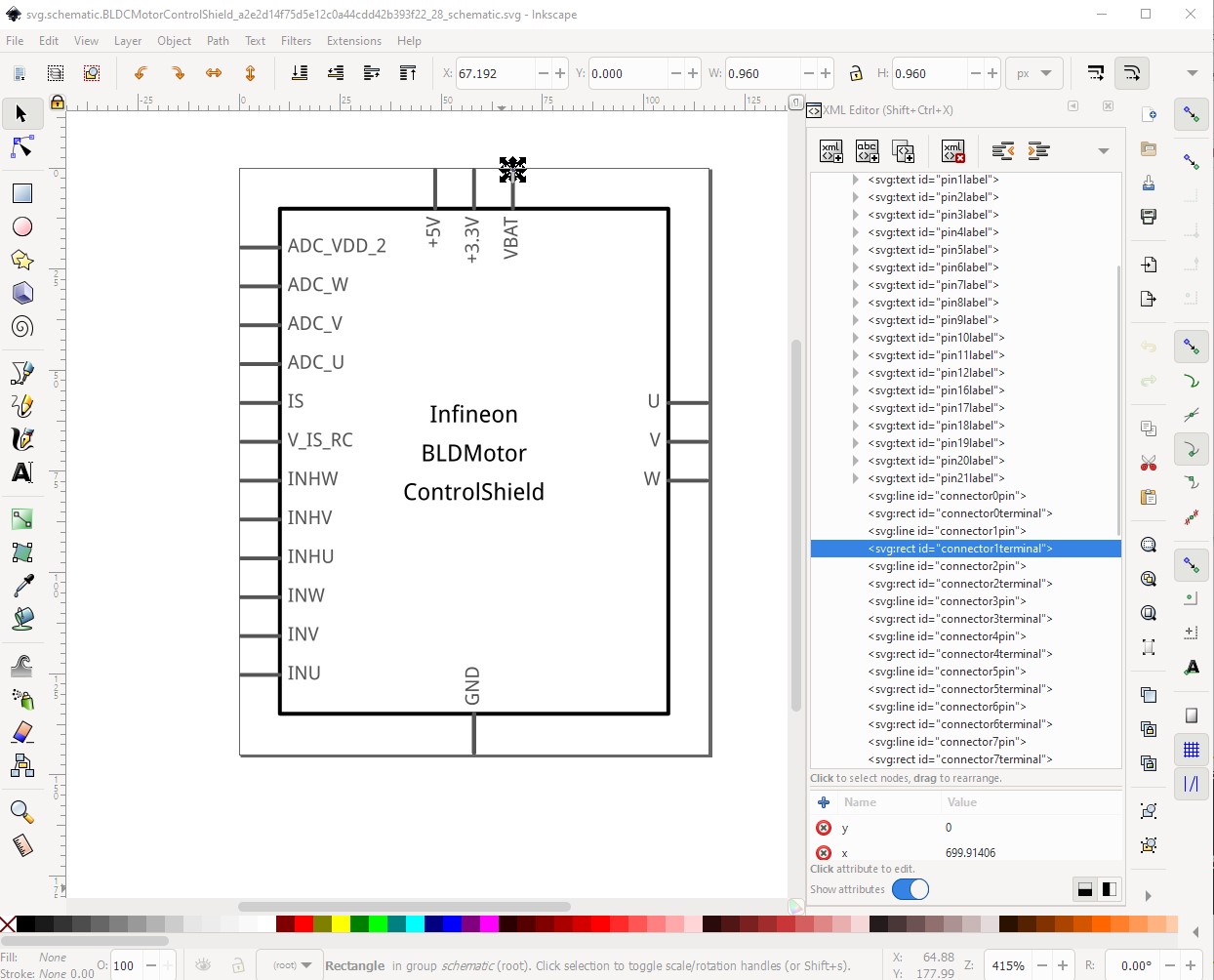
For schematic I chose to start again. The Eagle2Fritzing schematic is old in a variety of ways (0.2in long pins, colors that don’t match the current graphic standard.) In this case all the Arduino pins will be on the left, power on the top and the 3 motor outputs on the right. To achieve that I first figured out the number of ground pins needed (because they all need to be present even if they are on top of each other) and they need to be in the bus definition at the bottom of the fzp file.
connector0
connector4
connector5
connector21
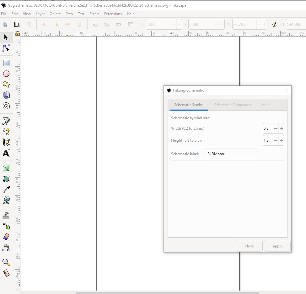
I started Inkscape (with no svg) and used the Friting schematic extension available here to make a new schematic:
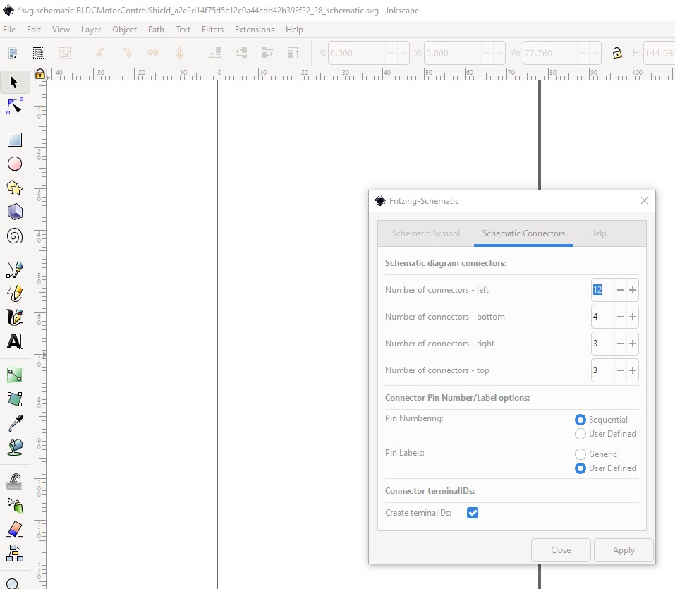
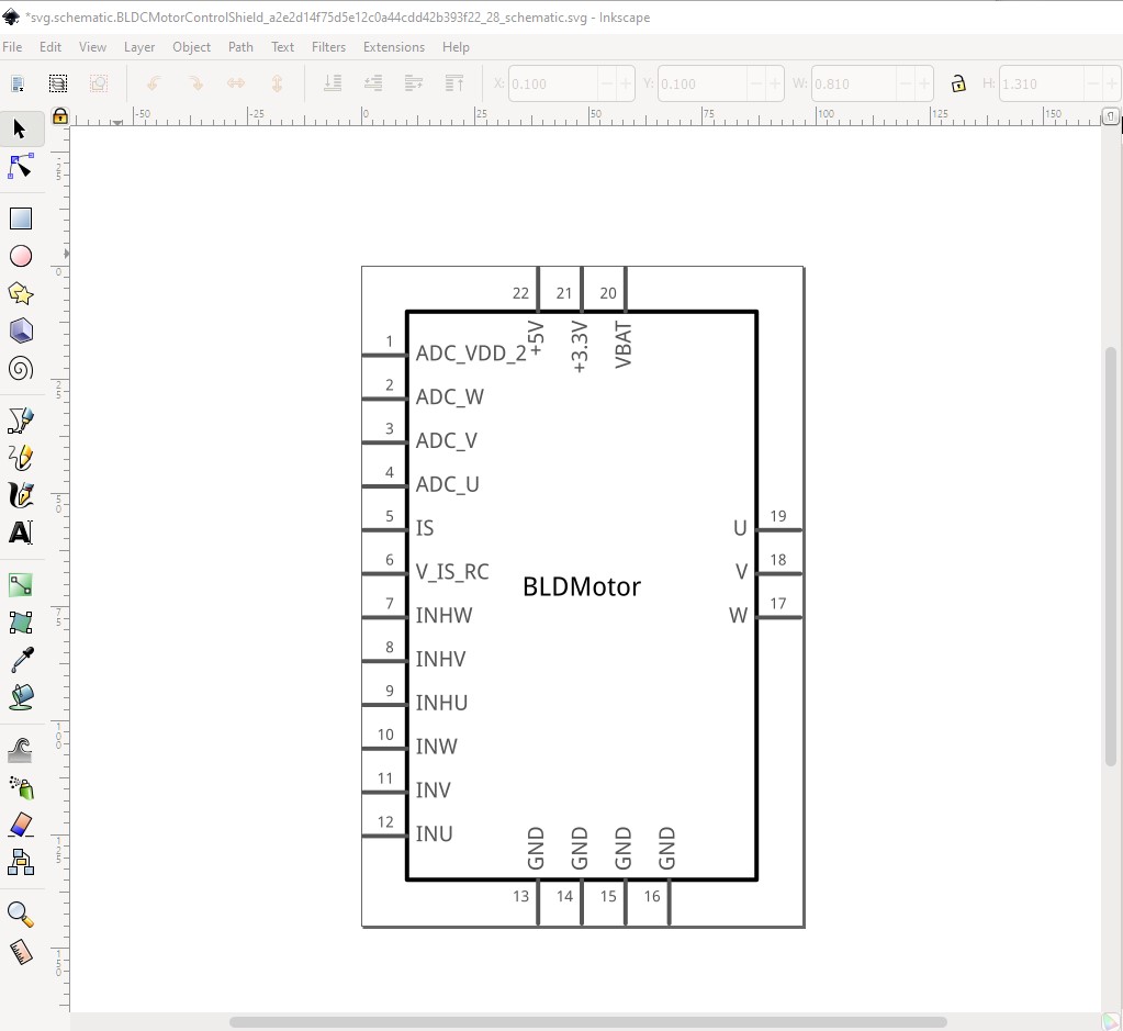
So I need 4 ground pins on the bottom, 3 power pins on the top, 3 motor outputs on the right and 12 arduino pins on the left. So my height needs to be 1.3in and width 0.8in. So start the Fritzing extension in Inkscape and set the dimensions and label (we will need to dup this later to get the rest of the label!) and set the box size.
then change to the schematic connections tab and set the pins this will be in the wrong sequence but we will edit it later, and we want terminalIds ticked because we want terminalIds defined.
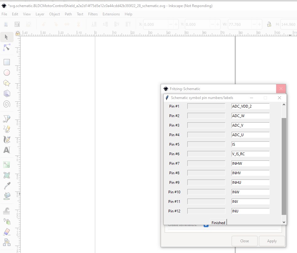
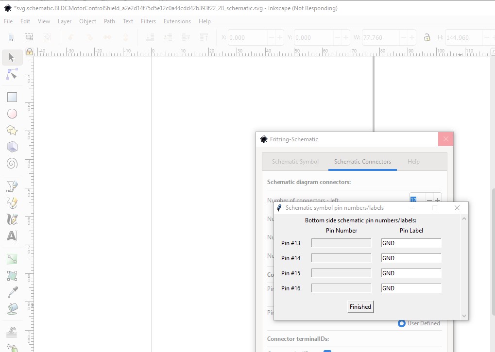
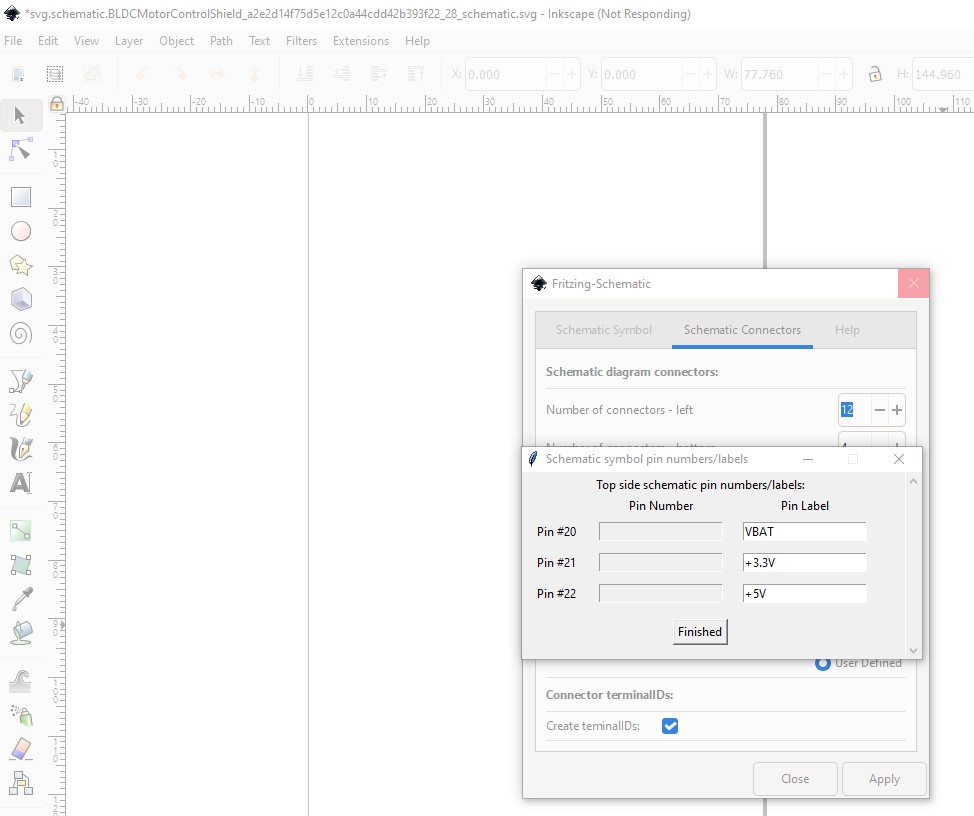
now hit apply and start naming the pins. I used the names in the fzp file to do this starting at connector6 (the first arduino pin) and skipping over the motor pins at connector12-14.
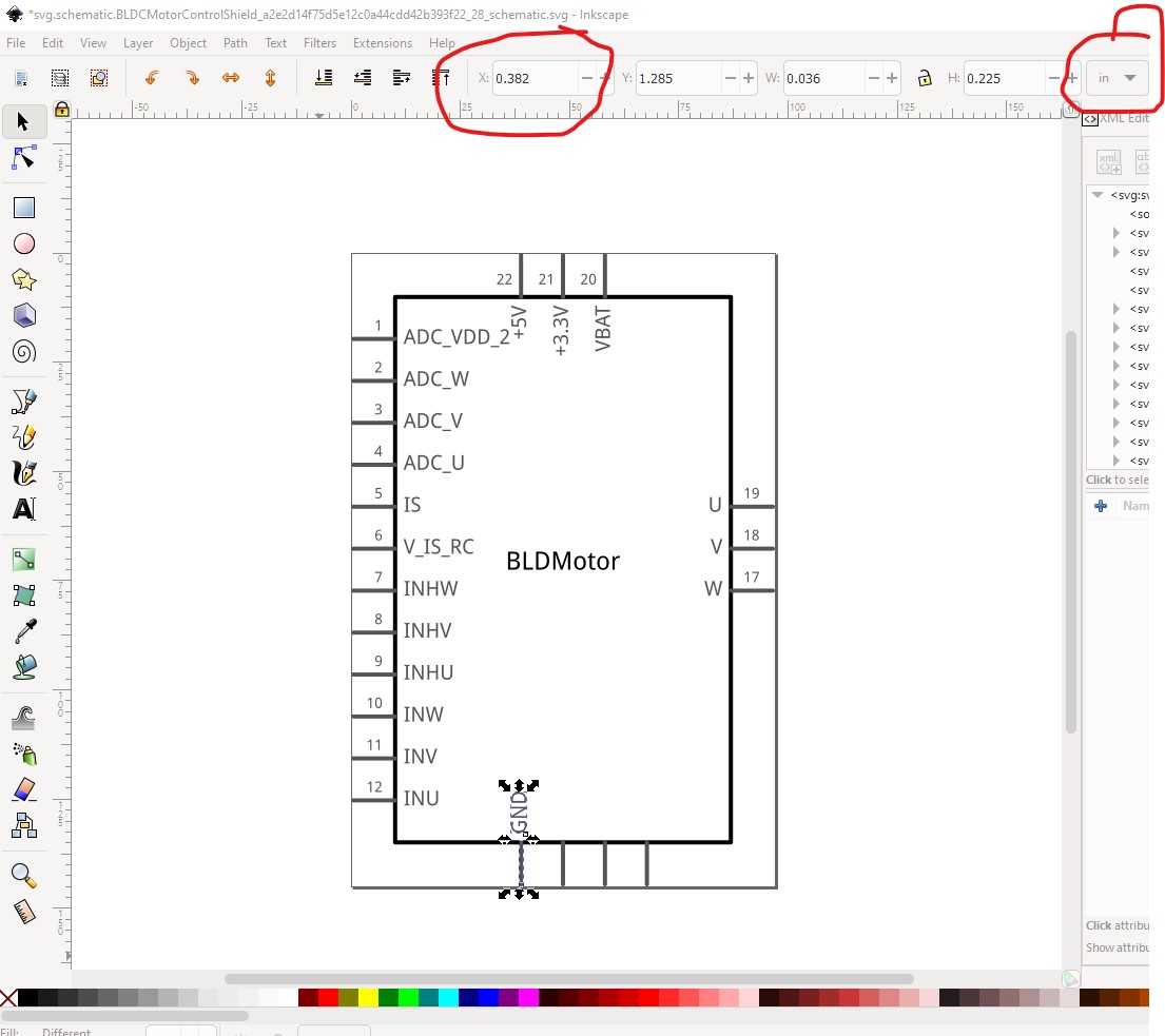
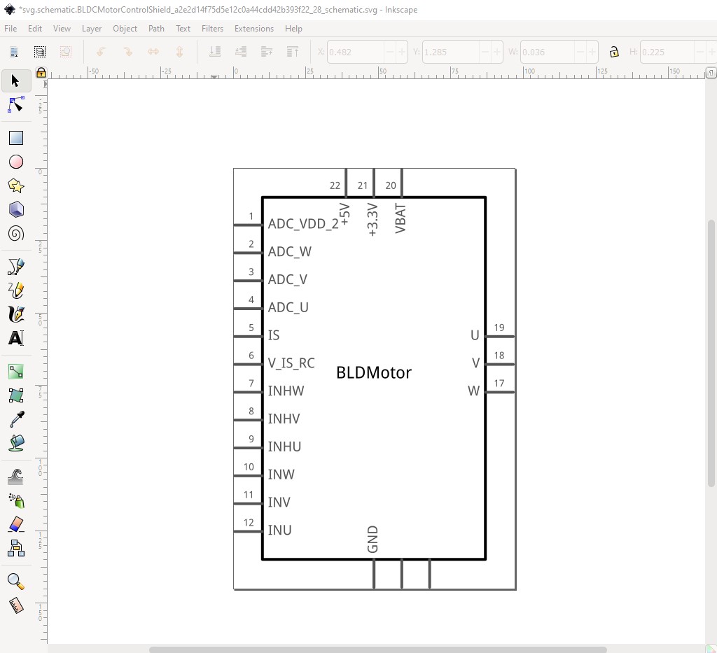
It needs some editing (and a pin number change!) to become exactly what we want. First 3 of the GND pins need to move over top of the remaining one so all 4 pins are on top of each other like this (3 of the GND labels and all the pin labels are removed!)
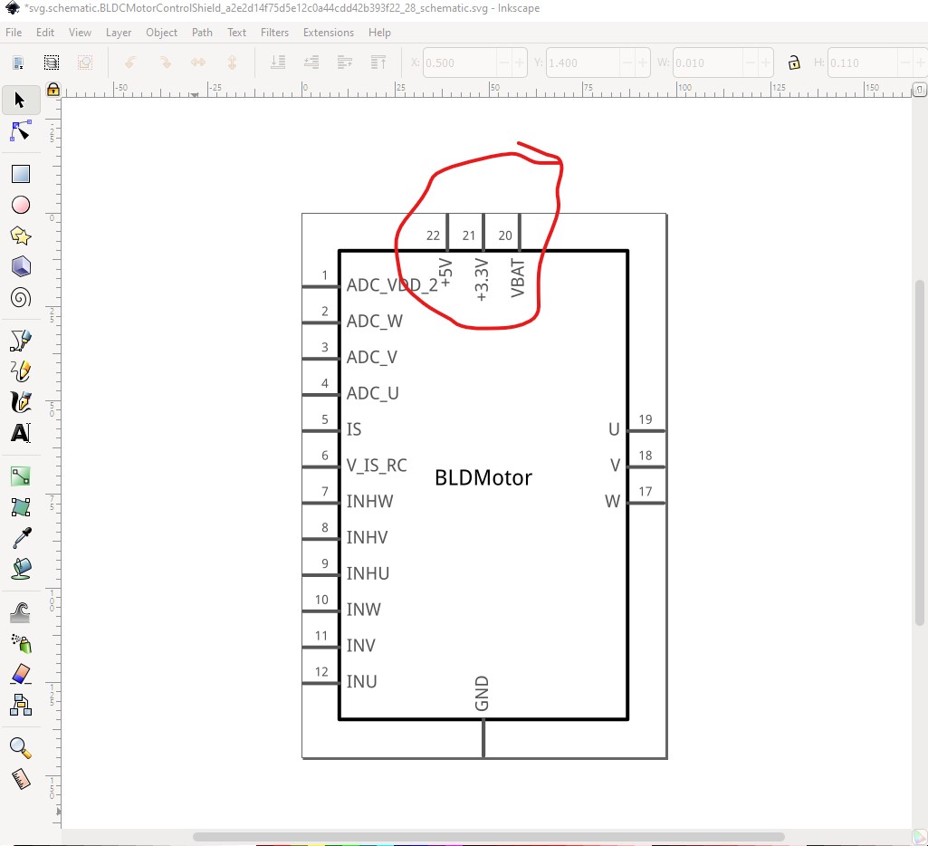
Note that I screwed up and the power pins are too close to the pin 1 label, so move the power pins and the rectangle .2in to the left like this, to look better. Then duplicate the label twice and move each down .1in to add the two missing lines from the original schematic and we have a correct looking schematic svg with inputs on the left and outputs on the right and power and ground on the top and bottom. Unfortunately the connector numbers are wrong (because the extension assigns them sequentially and we don’t want them that way.) There are a number of ways to fix that, manually (which takes a lot of time and typing) or my preferred method which is to move the pins in the svg in to the order I want them and use a script to renumber them like this:
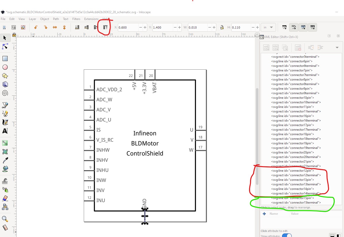
We need to start with connector12 which is the first ground and wants to become connector0 to match the fzp file. To do so I select both it and its terminalId (which will be 4 pins and 4 terminalIds as this is the overlaid ground pin) and move it to the bottom of the svg like this:
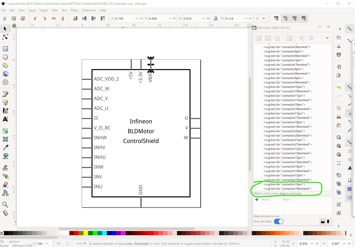
here the 4 ground pins (connector12-15) have moved to the bottom of the xml editor window (and the bottom of the svg file which is what we are depending on!) Connector15 (circled in green) is the new connector0, when I need a ground later the 3 pins connector12-14) above it will be used. Sine the pin numbers won’t be correct, are a pain to change and not that useful I chose to minimize work and deleted them all. Now reading the fzp file, connector1 is the VBAT connection, so select both its pin and terminalId and move it to the bottom of the svg:
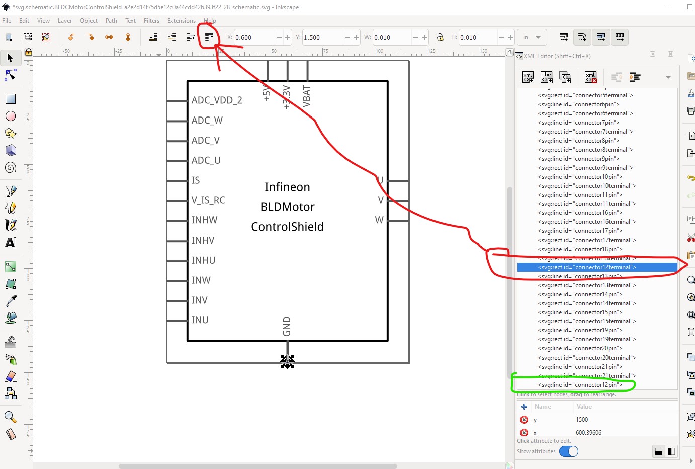
now do the same to all the rest of the terminals in order down the fzp file. At connector4 I hit another ground pin, so this time use xml editor to first select then move connnector12pin then connector12terminal to the bottom (because selecting the pin in the drawing will move all 4 grounds which isn’t desirable!)
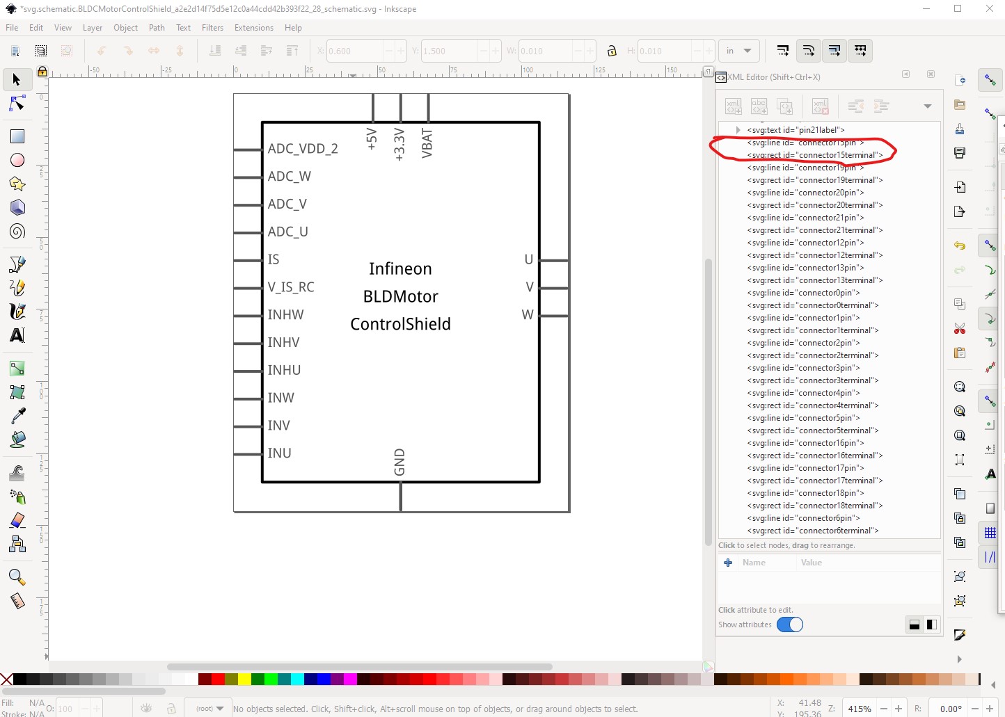
where the pins and terminals are in the correct order, but are not numbered correctly. As long as the first connector has “connector” in its name (and there are no other ids that start with connector higher in the svg) this can be fixed by a script I have (but haven’t released yet) like this. First save the svg as a file, in this case I will resize and group it first so it is ready to go. Then use a text editor (vi in this case) to check the expected connector is the first connector in the file:
the pins are renumbered and now (assuming I didn’t screw up of course!) match the pin numbering in the fzp file as they must. So we can go on to edit the fzp file to fix the buses and then test the new part to make sure it is correct. Currently the bus definition in the fzp file looks like this:
Now we need to deal with the pcb view not having connectors for the screw terminals (VBAT and its associated ground, and the 3 motor terminals), easiest to find in the breadboard svg:
with that in hand we remove the pcb pin definitions in the svg file as there are no associated connectors defined in the pcb svg which would cause a problem, like this:
then the same for the other pins. Then 3 more corrections: change all the pad to pin (because we used pin in the pcb svg) and all the type=“female” to type=“male”. The last will cause the connection dots to appear in all views. The last correction is to change the breadboard layerId from
Last but not least add a label field of “M” (for module) so the part will be M1 rather than the default Part1. With all that done run the result through FritzingCheckPart.py to see what I screwed up. Turns out I was not paying enough attention and forgot there are no terminalIds in the schematic definition for some of the pins (the part will be misaligned and the wire will connect in the middle of the pin!) so
With that FritzingCheckPart.py runs relatively clean and we can now test the part (note testing included exporting the pcb as gerbers and checking that the gerber output is correct, the holes are all 0.038in in the drill.txt file and the silkscreen rendered in the gerbers correctly using the gerbv gerber viewer!)
Hi,
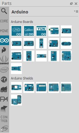
I see there are many boards listed in Fritzing like Aurdino, Sparkfun, Intel (Refer image)
in the same way i need to publish Infineon boards also in Fritzing.
Could you please guide me?
Thanks
Jana
Upload what files? Files for a part can be uploaded to the parts submit part here in the forum (upload is 7th icon from the left in the rely menu.) To be included in core parts you need to make a pull request against fritzing-parts on github
You would need to convince the developers to change the bin files to add your new bin (or publish a .fzb file for your new bin here) I believe it needs a code change to make it in to core parts and hasn’t been done in the 7 years I have been here.
I’m not in charge of making the above changes, you would need to contact the developers (who sometimes read the forums.)
If you want Infineon boards to be directly available to all users in Fritzing, you need to have the parts available. I suggest storing them in a github repository. After that, you need to communicate with the maintainers of the Fritzing Parts library, to have them added in. The issues page for GitHub - fritzing/fritzing-parts: Electronic components for use in the Fritzing app (aka the parts library) is the place to start for that.
As an alternative, you can store the parts someplace individual users can download them, for use in their own sketches. Once the parts are available they can be either posted to the “parts” forum here, or post a link to where they are stored. Done correctly, each of those options will end up creating a new ‘bin’ in the Parts view, that parts can be selected from.