Good morning,
I made a small circuit to test Fritzing (v1.0.2).
How to have round drilled pads rather than undrilled rectangular pads for the component insertion locations?
Thank you for your reply.
Note: I read the posts that talk about ‘drilled’ but I didn’t find any solutions to my problem.
test fritzing 4a2.fzz (11.4 KB)
Most parts don’t allow switching the footprint.
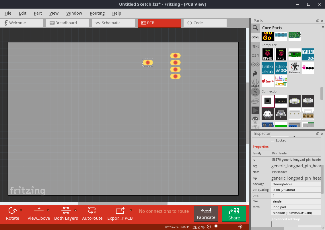
However, for example Headers (in the “Connection” section in the parts bin), are available with various footprints, like an oblong THT connector:
Thank you for your quick response.
What is annoying is not the shape of the connectors but the fact that they are not pierced.
When I export for production, only the round pads are drilled.
In this case your problem is that you have selected SMD components which have pads rather than holes. Changing the resistors from SMD to THT in Inspector will cure your problem.
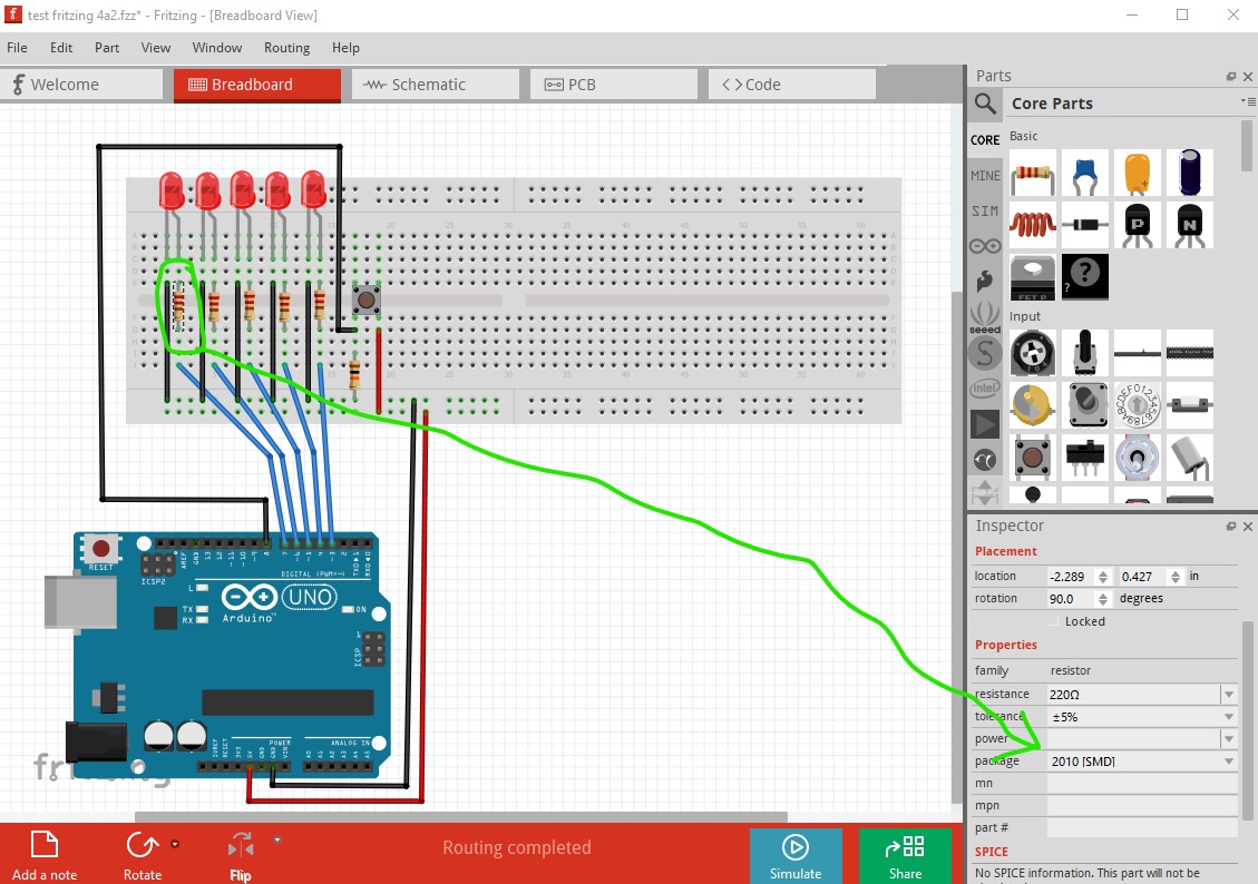
which in pcb generates a pad with no hole.

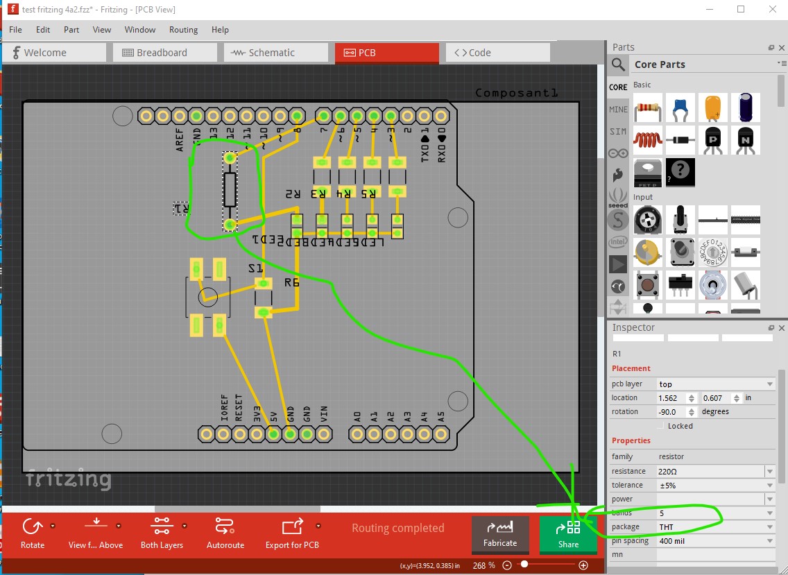
changing that to THT in inspector makes a resistor with pads with holes (but because it is connected to SMD components it will only route on the top layer and thus the traces overlap!)
Peter
It works perfectly. Great, thank you !

Good evening,
In Fritzing, the pcb is well drilled but in the Gerber files created, there is no one for the holes !
I use FlatCam (at least I try) to create toolpaths to control a Genmitsu 3020 pro max CNC (for creating g-code).
The milling for the copper and the contour are ok, it seems to me.
Later, I will use the possibility of engraving the list of components on the other side.
The gerber drill.txt file should have the hole positions. If you upload the sketch (the .fzz file, upload is 7th icon from the left in the reply menu) I can create gerbers and make sure all is well. Gerber processing takes place after the images are rendered in Fritzing and some errors can affect only the gerbers.
Peter
test fritzing 4a2tht.fzz (13.1 KB)
When I open the txt file with FlatCAM, I get a failure message. Gerber format is not recognized.
Thierry
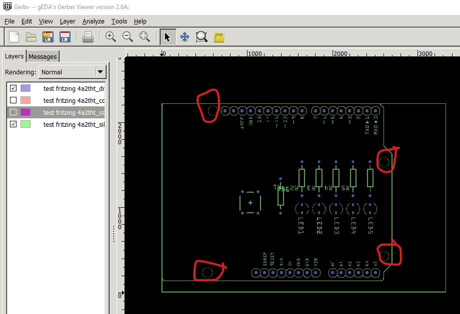
Works fine for me, the holes (except the mounting holes) are all drilled fine.
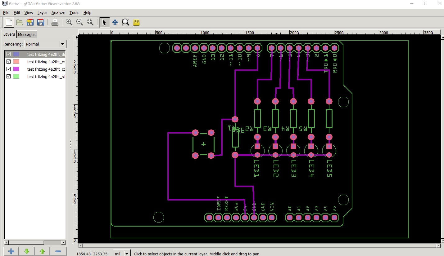
this is just the silkscreen and drill layers as noted the Arduino mounting holes aren’t drilled you need to drag a hole in to the sketch to get them drilled)
I’m not all that familiar with what is needed for CNC output but there are forum posts from opera_night on what worked for him (he has moved from Fritzing to Kicad but made it work in Fritzing before that.) As far as I know the gerber output is standard I’ve never had a problem with the board house with Fritzing output.
Peter
Thank you for the answer.
I’m trying this tomorrow. Um, it’s already tomorrow!
Good night.
Good morning,
I found the solution for holes in Flatcam. The .txt file is not opened as a Gerber file but as an Excellon file.
The result is absolutely perfect!
THANKS