No, this won’t drill a hole. The reason for putting the hole on the silkscreen in the part is so the hole is not there in the case where the user doesn’t want the hole (such as to run traces across where the hole would be.) If the user wants the hole, in the sketch (which is user modifiable unlike the part) they can drag the “hole” item from core parts pcb over the hole in the silkscreen to actually drill the hole. That way you don’t have to modify the part to remove the hole (a Fritzing oddity.) Here is an example with a random part with mounting holes on silkscreen only (note you can also define the holes in the part!):
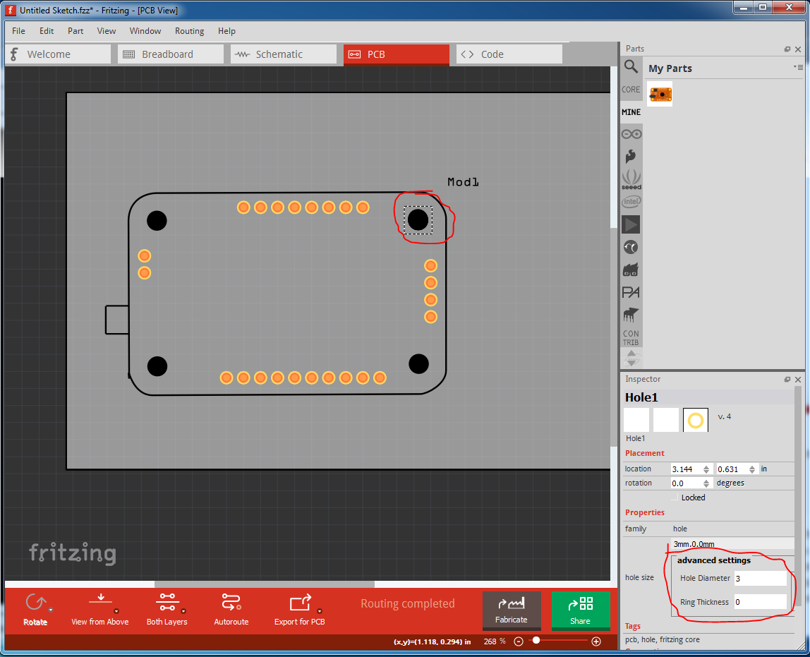
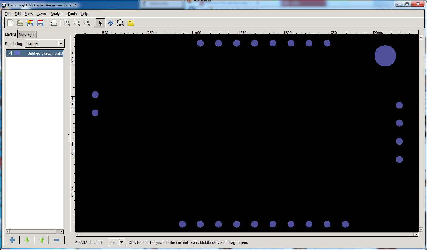
Here I have moved the hole on top of the original hole in silkscreen. While this looks identical in Fritzing, the difference shows in the gerber drill.txt file:
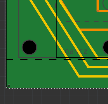
Here only the mounting hole I dragged the hole on to is actually drilled, the other 3 are still only on silkscreen layer. If you want the surround on the mounting holes (which will be copper) in crease the size of the ring thickness in Inspector to the desired size (it is currently 0, no ring.) Always check the gerber output files with a gerber viewer before ordering boards, because the gerber output is a stage after pcb view and sometimes will be different than how the board appears in pcb view (as this case illustrates!)