Hi,
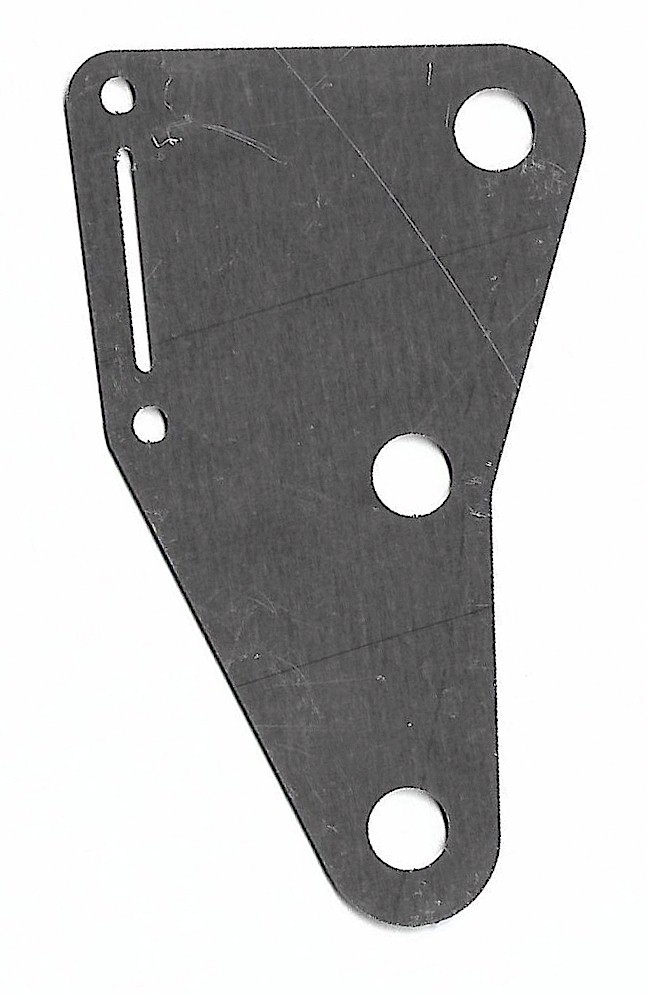
I’m a casual user of Fritzing and am attempting to make a pcb board with an angle opening. I really appreciate any help anyone can provide. I’ve got the basic *.svg shape into Fritzing and am thinking I may have to use another software to draw this angle cut out. Attached is a *.jpg of the board. What I have in Fritzing is the basic shape. Is there a way to cut the angle in Fritzing or do I need to do it in another program?
The outline and the holes aren’t a big problem (not easy but possible with enough work) but the slot may be a problem. As I understand it (I rarely make boards) the inexpensive board houses don’t do slots. What you are looking for is to make a custom board outline svg (which is not all that easy.) If you search for “pcb shape” in the forum search bar there are a number of articles about how to do this.
I’ve created custom pcb shapes a few times. I don’t find it that difficult, either with manual svg editing, or with Inkscape (I don’t have access to Illustrator) but my instructions don’t seem to work for others.
Any svg editor or modifying the text file with a text editor should do it. The tricky part is getting the single additive subractive path that it wants. Then even if the shape appears fine in Fritzing, export the file as gerber (File->export->for production->gerber) and check the result with a gerber viewer (I use gerbv from the Geda project but there are lots of them.) The gerber processing happens after the rendering in Fritzing and has some bugs which sometimes cause bad results. Using Fritzing 0.9.6 is preferred because a lot of the bugs got fixed there (although you need to make sure there are no -e type elements in the path, that is a bug in 0.9.6!)