after prototyping on a breadboard I want transfer the design to a double sided breadboard sold ba ebay, aliexpress etc
Now I’m looking for a fritzimh part like the one in the picture
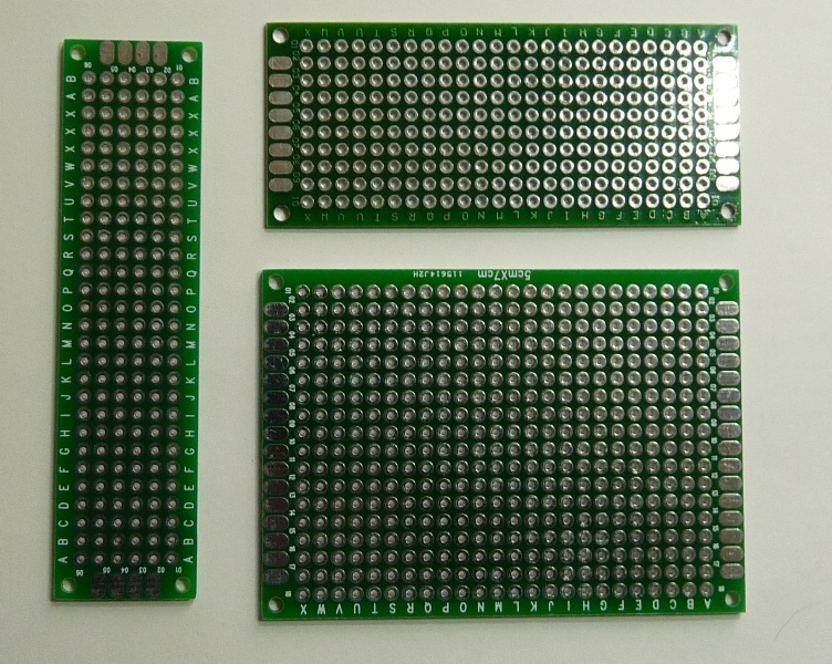
Any hint where I can find those parts.
Thanks
after prototyping on a breadboard I want transfer the design to a double sided breadboard sold ba ebay, aliexpress etc
Now I’m looking for a fritzimh part like the one in the picture
Any hint where I can find those parts.
Thanks
Not exactly, It is not double sided and does not look exactly like the ones in the picture. If you click on Core Parts, about the fourth category from the bottom, then click on Basic Single-Sided Perfboard. It is sizable, you can select the number of columns and rows.
steelgoose
thank-you! Great step towards what I’m looking for 
As the boards I’ve shown are verry cheap, double sided and aviable from differnt sources (ebay, aliexpress etc) it might be worth the effort to alter the Basic-Single-Sided Perfoboardsto to fit the “real existing ones” .
Being a newbie I’m not / feeling not able to take this task 
(Found horrible stories about creating / changing fritzing parts …)
Thanks!
I’d say it isn’t worth the effort to do this. The resizable board code is part of core and while we might be able to fool it in to accepting a different image, the addition of only the tabs on the end (which would need to be resizable too which won’t be easy or perhaps even possible without a code change) doesn’t buy us much. I have a bunch of these boards in the various sizes and just use the current perf board adjusted to the row and column count. Breadboard view (unlike pcb which has been suggested as the better place for this) doesn’t really support top and bottom layers so the dual layers aren’t that useful (in real life the plated through holes are invaluable, but in Fritzing not so much).
Peter
Peter
thank-you for sharing your inside view.
As fare as I know there are just 3 different sizes of the boards in question. So my thought was to handel them like the original breadboard parts where you have a limited number of varieties. So no need for resizeability, just tree (?). I’m not familar with the design process in fritzing as I said before but having some experience with other grapical design programms maybe its possible to have a basic design of some rows and colums with endpads and mounting holes. With this at hand you can add or delete rows and/or colums (just representing the holes) easily.
I agree one can do everything with the generic perfoboard however one among others great features of fritzing is it visuable representation of the parts in use.
Btw Beside the tabs at the ends the boards have very usefull mounting holes too ad the ends. A very practical feature. you may have noticed as you said you have a bunch of these boards.
As a fritzing newbee I’m sorry for not beeing able to do the job for me and the community - may be with the help and guidance of a patience user.
Peter thank-you
I personally don’t see a use for perfboard in Fritzing but if you really do need to prepare for building on a perfboard you can simply use the PCB view with the grid size set to 2.54mm (0.1") and then all the parts you place will end up matching the perfboard layout so you know the parts will fit. If you really want it to look like an actual perfboard you can make one using headers and a pcb in PCB view. Here is the 6x30 board from above Perfboard_6x30.fzz (1.7 KB)
. Please do note this is just a work around so it is not ideal but it will give you a pcb with holes in it to work with. You will either need to ignore the header pins in schematic and breadboard view or maybe make the board out of single row headers (I used double row) and then lay them out in a grid in schematic and breadboard view.
Thanks sublimeartisty,
thanks Peter,
here are my 5 cents (INKSCAPE .svg)
Maybe someone with more skills than me will take the task.

Hope its usefull 
The difficulty with the above is that it is only one of the svgs and likely without the necessary pins. I have around a dozen different sizes of these boards (and that is by no means all that are available). Taking a common (small!) size 10*24 pad version that is 240 connectors on top of the 240 pads needed in both breadboard and PCB (it doesn’t need schematic) and then the 480 connections for both those views in the fzp file. Now we need to add on the 8 pads on either end and the 4 mounting holes and ideally the lettering of the rows and commons. Now multiply this by a dozen or more. The only practical answer is either a code change (which I’m not capable of and I doubt is a high developer priority given some of the bugs and finishing part editor) with an unknown release schedule or an external script (which is the more likely if not much less work solution) that creates the fpz and two svg files needed for the board from an input specification (likely the x/y coords of the mounting holes, the number of rows and columns of pads and the number of the edge pads) which generates a different new fritzing part for each board (which is potentially a fair number of parts). I for one don’t see the demand for that much work, the current method does %90 of what that solution does and is available today with no work required.
Peter