Please also attach any files that help explaining this problem
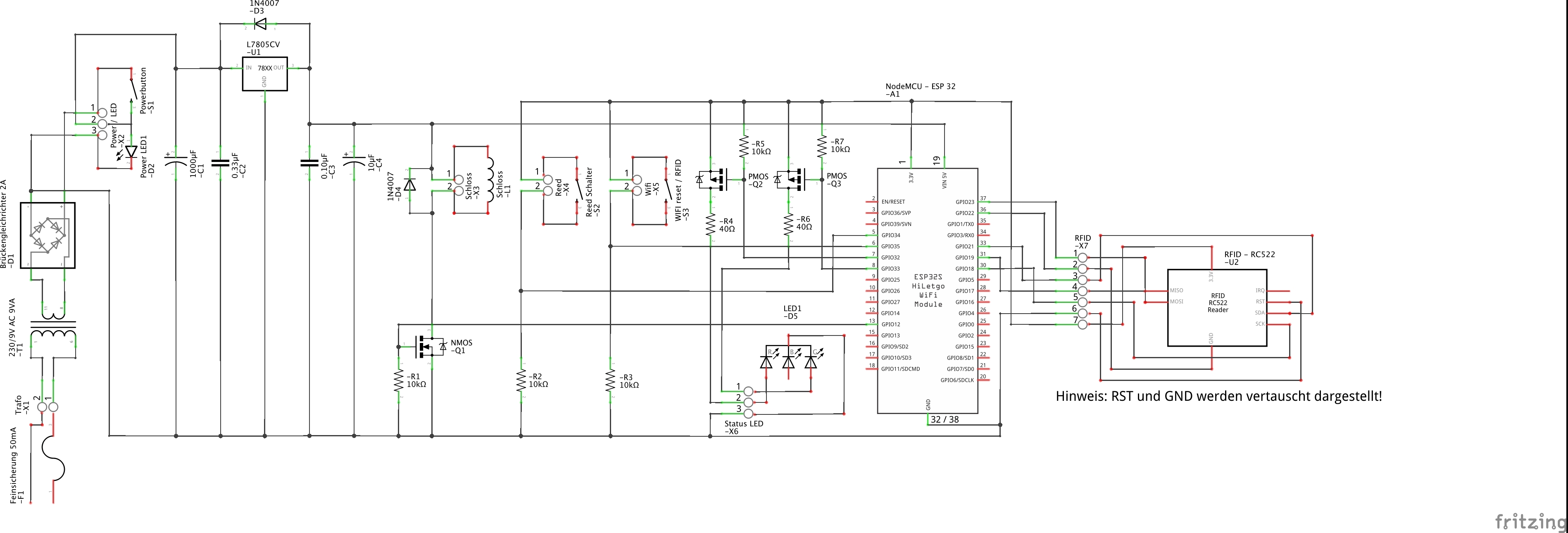
Hey dudes. I want to export my electric circuit as SVG file but Fritzing doesn’t export the ESP32 part. I’ve tested it with different parts of the ESP32 and also on my ubuntu pc but no one will export it right. Its always empty in the SVG files. And some comments are also missing. Is there any workaround to fix that?
The ESP part is misconfigured (it lacks a schematic layerId.) If you would upload the .fzpz file of the ESP part (upload is 7th icon from the left in the reply menu) I’ll fix the part up for you. Right clicking on the ESP part in your mine parts bin and right clicking then export part will write the .fzpz file to the file system if you loaded it directly in to Fritzing.
Yep, that is what was needed. The problem is that breadboard and schematic layerIds have a capital in the svg but not the fzp file. This works on Windows (which is case insensitive) but not Linux or the Mac (which are case sensitive.) Both are fixed in this part:
edit: replaced the original with the correct part …
The capital S needs to be lower case to match the .fzp file. To replace your current part you need to select it in the sketch then right click and click “delete minus”. This deletes the part but leaves the wires connected to it. Then you need to right click on the part in the mine parts bin, right click and select delete. That should entirely delete the part but does not. Now you need to shut Fritzing down and restart it to really delete the part. Now you should be able to load the part above and drag it in to the sketch. Then you need to click the end of each wire in turn and move it a bit til the connection on the part turns from red (unconnected) to green in all three views. Sometimes I find it easier to just delete the wire and re run it than trying to get it to connect, but whichever is easier.
Hmm are you sure, that you’ve choosen the right file because it doesn’t match with the old one on my circuit and pcb layout? I can’t replace it one on one like the way you explained.
Thanks, now the ESP part looks perfekt in the svg file.
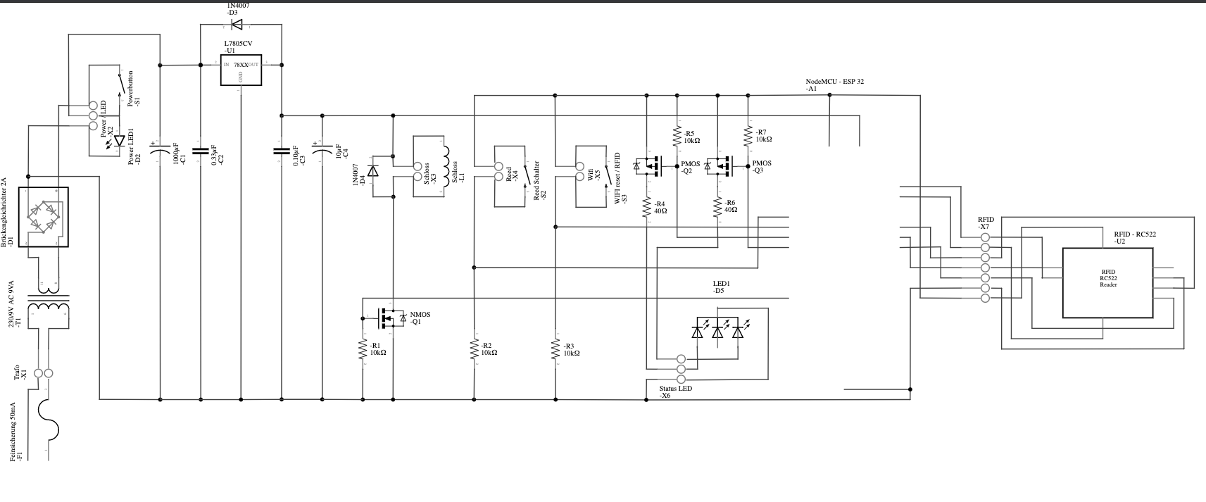
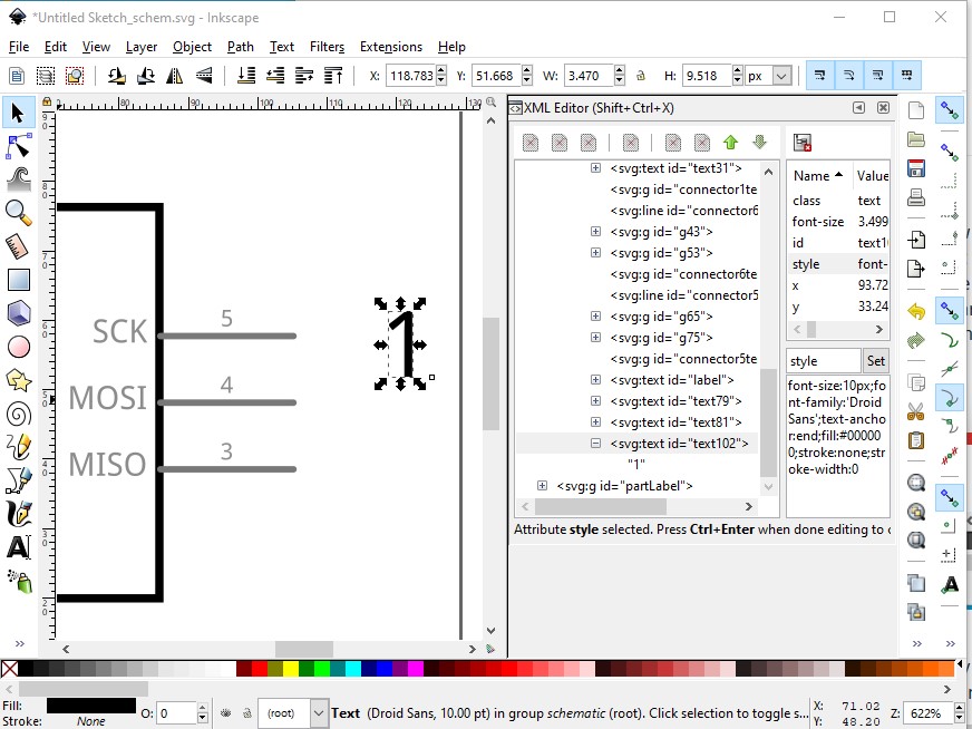
Now there is one more thing missing in the svg file. You see in the jpg file above on the right sight a txt field which is in the svg missing. How can I fix this?
As far as I can see all the pin labels are present and correct (at least match breadboard and pcb) except maybe pin 18 which is shown as GND (but is really GPIO11 in this case) in breadboard. Can you provide the pin number beside the text you think is missing?
Did you mean the pin numbers of your fixed ESP part? This one is now correct and matched perfect with our ESP Devkit C Board but for example on the right sight there is the the screw clamp connection which name is “RFID -X7” and the numbers of the pins. The numbers are only text fields which I have added manually from the core part but all the numbers are missing in the svg file. You can see it in the first jpg file I have uploaded. You will see in the underlying svg file they are missing. I hope you understand what my problem is?
here I just duplicated one of the text labels, moved it and changed the content and font size in Inkscape to add the text. I’ll check if schematic text not being exported to the svg has been reported yet and report it as a bug if not, but it will take time to get fixed.
An alternative that may be somewhat better is to modify the rfid part to add the needed pin numbers to the connector inside the part (I can do that for you easily enough if you post the rfid part you are using.) If it is in the part it should avoid this particular bug and you don’t have to re edit the svg every time you make a change to the sketch.
That would be realy nice but i don’t want steal all of your time because there are some more parts which has not the correct number or it is missing in general. I will have a look tomorrow to edit it by myself with inkscape and if i fail i will message you again.
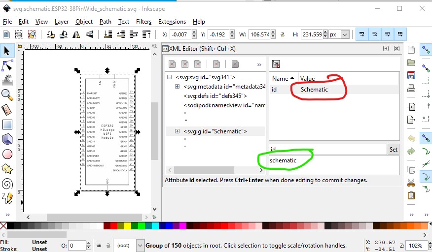
Is there anywhere a tutorial how to edit the fzpz files?
Not tested with this case, but what I see in the thread is that the example text is outside of the normal extent of the part graphics. I have previously seen that causes exports to ignore the text. Especially for cases where that is at the edge of the drawing. Depending on the text origin and alignment, it can get excluded (clipped) as being outside of the area to be processed. Due to the offsets used in svg for text positioning, text can “appear” to be inside the extents, but the actual origin is outside. This is mostly seen for the top line of text, and on the right edge.
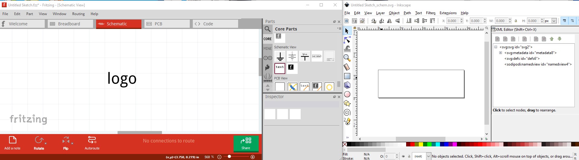
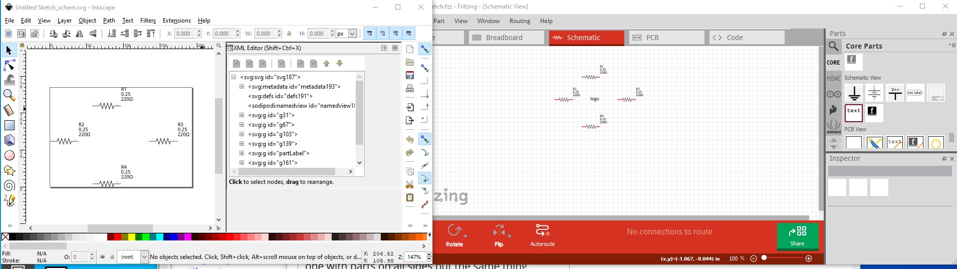
This is a different case I think. Here the text isn’t in the part, but is rather the “text part” from core parts/schematic. The part gets exported, but the “text part” doesn’t. The text shouldn’t depend on the viewbox of the part. Here I only added the text to schematic and exported the sketch as an svg. The text doesn’t make it in to the svg:
Where is that text part relative to the remain parts for the view? If it does not have normal part graphics on every side of it (so it is inside of the bounding box for parts), it could be excluded from the exports based on some research I did a year plus ago. Still a bug, but could narrow the scope of the problem some.
so then I exported the sketch and unzipped the .fz file. There it appears to make a part which looks fine (layerIds all present as they should be) but it somehow doesn’t make the export.
in the resources folder of the Fritzing source directory. This may be a clue however:
<schematicView layer="schematicText">
this changes the layerId to something that doesn’t match the svg, but changing it to schematic makes the text not display in Fritzing, so it may or may not be the issue.
There is a “Text Layer” on the view menu. Which testing shows is where the text part goes. So perhaps the export code is excluding that entire layer. Which is likely just that text part.
doesn’t match the svg? schematiclogo.svg? I would “expect” that that fzp layer should match the referenced svg file. Cases where it does not is where we have seen export failures before. Only content from the part svg file that is on a layer that is specified as a layer in the fzp file for the view ever gets exported. “schematicText” could be special, but it is suspicious.
I wonder if content could be put on the schematicText layer in a part svg file (and included in the layer information in the fzp), then visibility controlled by the “Text Layer” toggle? Missing (as is common) information about what the text layer is intended for. More undocument special names.
That looks to be the secret. BB and PCB don’t have a text layer and text exports to the svg in both. In schematic if I disable the text layer in View the text indeed disappears so it looks like that is the issue (which should make it easier to solve!)