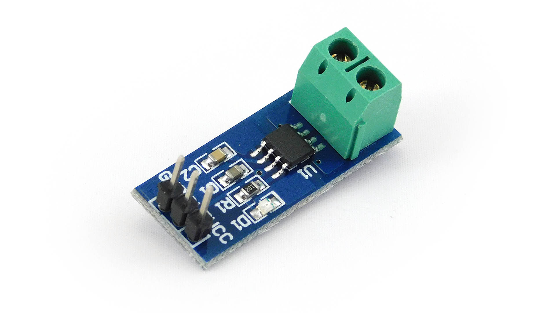
I need Current Sensor ACS712 part of the image following…(width 13mm and length is 31.2mm). I am newbie and I can’t build parts. Do anyone have this part? please help me out. 
As always google is your friend (and the first place to start when looking for Fritzing parts). A search for “fritzing part ACS712” turns up a variety of options. I’d use this one (his parts are generally decent):
http://omnigatherum.ca/wp/?p=338
the web page is a bit weird, you need to right click on the text and select “save link as” to download the .fzpz file for the part (file->open in fritzing will load it.)
Peter
1 Like
Thanks peter. I searched in google. I found this link but i could not get any access from my country . Don’t know why !!! So now i am going to use vpn . Generally I don’t use 'em.
1 Like
Another version is here Current sensor 5A ACS712
1 Like
Tag Peter,
Habe Probleme mit einem Sensor ACS712 Fritzing Meckert beim Überprüfen der Abstände…
ich habe die 2 Version mit den beiden Löchern ober und unterhalb des OPs….es sind die Anschlüsse für die Datenleitungen zum Controller gibt es kleinere oder kann ich diese Fehlermelung ignorieren und die Platine zum Ätzen geben?
Danke dir für deine Rückantwort….habe immer noch die 1.04..
The best bet is to upload the sketch (the .fzz file, upload is 7th icon from the left in the reply menu) so I can have a look at what is happening in the gerber output. It is difficult to say that it will work without data.
Peter
Guten Abend peter hat sich erledigt….habe einfach eine 3er pinleiste verbaut…
mal was anderes gibt es mehr Widerstände? ich stoße gerade ans limit,…von 1.04
hätte gerne 20k -16k gibt es diese auch?
Yes, you can just type a value in to inspector like this
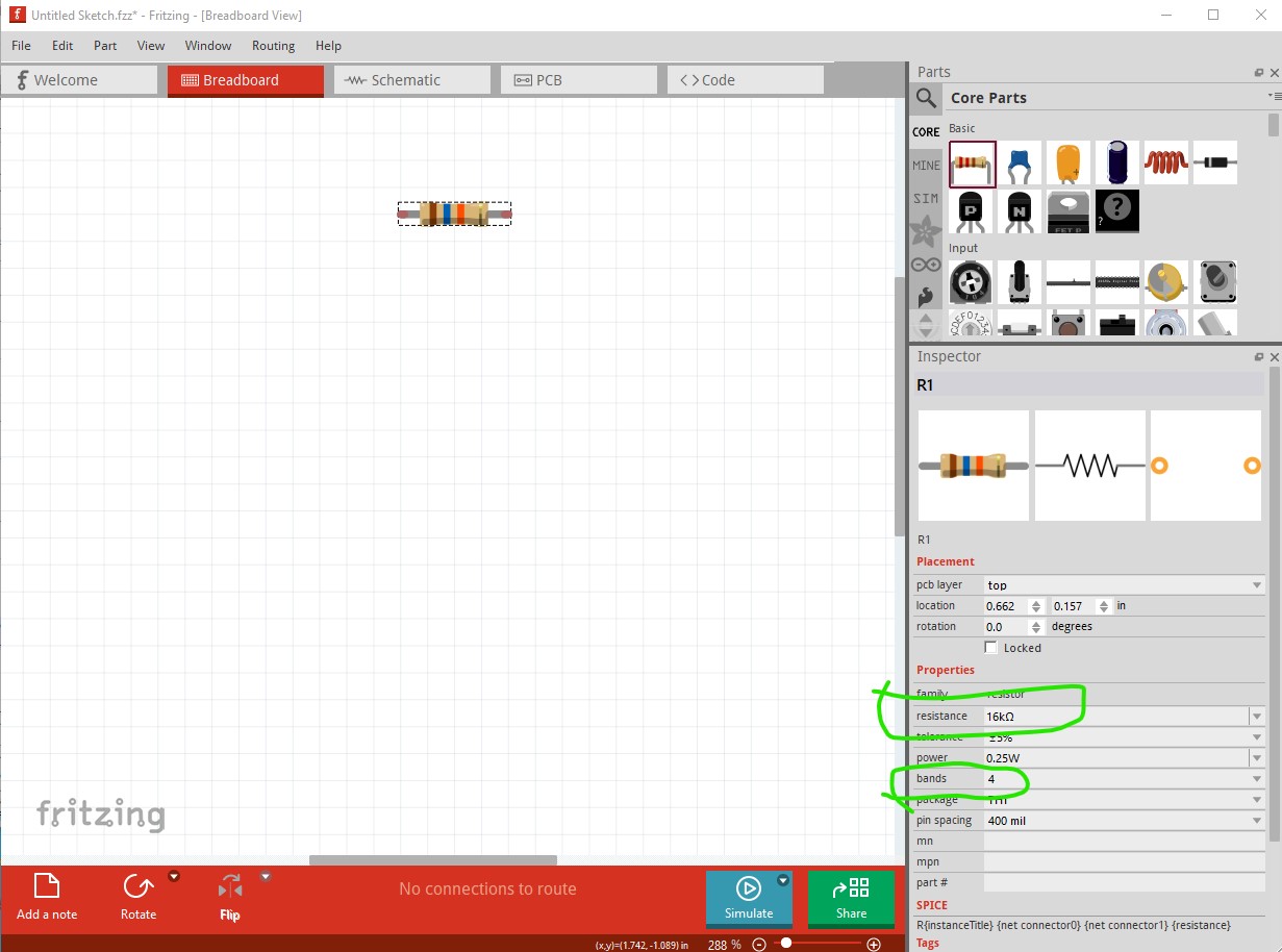
if you need more precision you can change the bands from 4 to 5 I believe to increase the range.
Peter
guten Abend Peter,
das habe ich schon alles durch es Bringt nichts…ich suche einen 20K und einen 16K
zur auswahl steht nur 22K….da ändert ein 4ter Farbring nix nur es wird genauer…
da dann kein Kohle widerstand sondern ein Metall widerstand draus wird…mit 1%
hat die 1.06 ein paar mehr zur auswahl?
Typing 16K in to Inspector changes both the value and the color code for me.
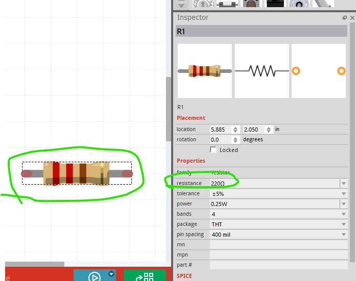
here both are currently 220 ohms. Here after typing 16k in to the value and selecting another field in inspector (to trigger the update) it changes the value and the color code to 16k

edit:
1.0.4 works the same way (I think 0.9.3b works this way as well, it is not a new feature.)
Peter
AH!!!
sogeht das…. wie beim ändern von Bauteilen mit einer anderen Bezeichnung ich ging bei den Widerständen davon aus das man diese nur Auswählen kann das man diese auch so bearbeiten kann inklusive Farb änderung! Super damit wären meine Heutigen Probleme gelöst
Danke dir Peter
Tag Peter,
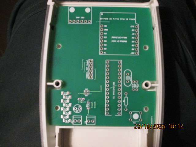
Ich wollte dir mal meine Schöpfung mit deiner Erstellten Platine zeigen.
Mein Daten logger kam heute mit meiner Post….sieht Prima aus allerdings musste ich die eine
Bohrung noch ein wenig Vergrößern das fällt aber nicht auf da dort eine der 4 Befestigungs
Schrauben die unebenheit abdeckt…
wegen mir könntest du mal noch einen Versuch starten um es zu ändern wenn du willst….
ab er wie gesagt es sieht man nicht… kann aber auch dem Gehäuse geschuldet sein das die Bohrung nicht sauber gebohrt wurde..
Grüße und Danke für deine Arbeit
Hans Werner
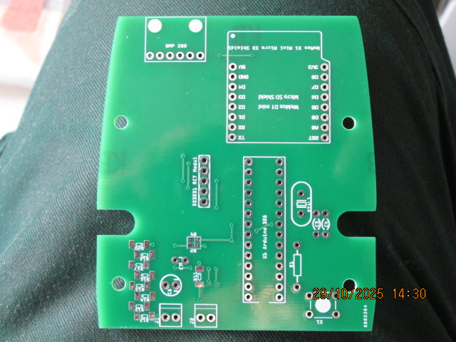
I assume it is one of the four mounting holes circled in red here
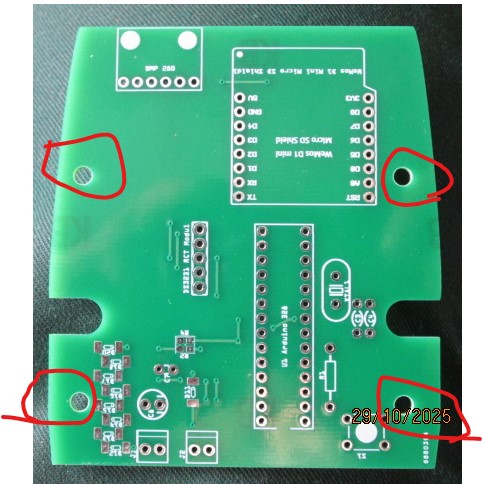
If you tell me which one I can look at the path and see if I can identify which hole is wrong and correct it.
Peter
Guten Abend Peter Rechts unten…bei dem Taster täte sagen 0,4-0,5 Zentel eher 0,3-0,4. nach rechts! das dürfte reichen…
Do you remember the post that the original board is in? I don’t immediately see where the original board is in my collection of parts and it doesn’t seem to be in this thread. Or you can upload the outline.svg file for the board that I made that should do me as well. It should be easy to correct the holes to match the case when I can find the svg ![]() .
.
edit:
OK I found the original post
I’ll pull down the svg and modify it slightly to fix it up so it fits properly. I see there is a mechanical drawing of the pcb but I will use your picture to move the holes.
Peter
OK I think this svg should correct the mounting holes.

Please try it and see. You should be able to print out the pcb footprint and compare it to the current board, both the holes on the left have moved slightly to match your photo above. I’m not sure if the silkscreen will match the svg but I think that it should (it appears to work correctly in the gerbers.)
Peter
werde es mal ausdrucken und überprüfen….dürften nur ein paar Zentel sein
erstmal Danke für deine Mühe
bis dato gut Nächtle!!
Ah!
I didn’t have a translator….
this is the original file….
