Hi,
Need the following component 20 PIN in exact dimensions for PCB manufacturing
Thanks.
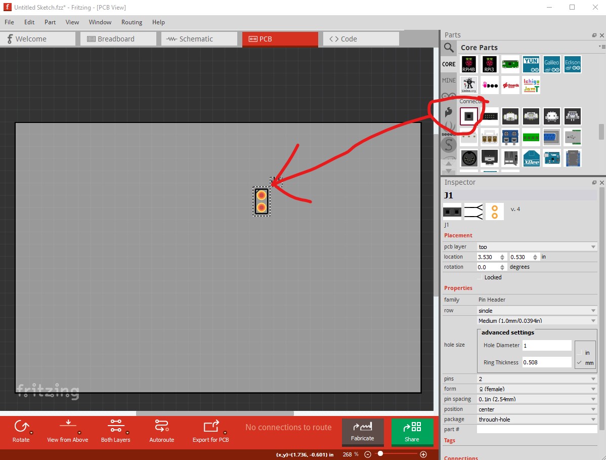
From core parts drag a connector in to the sketch
then left click on the connector in the sketch to select it and in Inspector (the lower right window) set the number of pins (20 in this case.)
then again in Inspector with the connector selected change single to double
and the appropriate pcb footprint is generated
note breadboard will still show as a single row 20 pin connector, it doesn’t do double row connectors.
Peter
Thanks for the support