I think the image for the breadboard and the image for the schematic should match in the diode’s direction.
In the breadboard image the cathode is on the left, anode on the right. While the schematics image is the other way around.
Just flip the diode around…
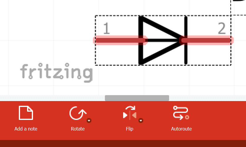
by pressing the “flip” button…
The developers have desynced flipping and rotating parts for a good reason – so that you can line the schematic nicely (for e.g. you have little space to insert a diode in the schematic view so you have to flip 90° but you don’t want to affect the other views
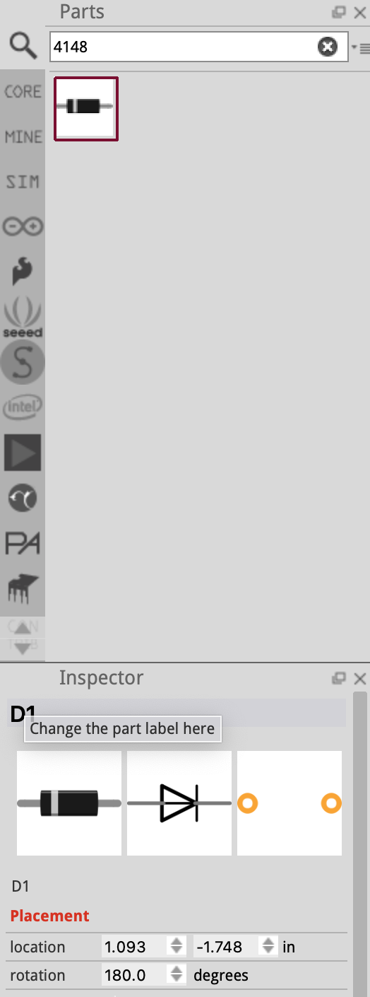
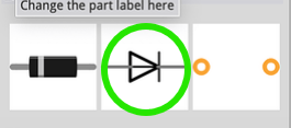
Edit: Unless you are referring to this (where they should flip it around)
Then I’ll submit a new issue on GitHub for sparkfun diode, part 4148
Yes I‘m talking about the lower part. Sorry for not making that clear.
Wait so you are referring to the one in the inspector view? (just to confirm)
Actually I wonder why SparkFun created another diode when there is one in the core parts?
Anyway, if you are referring to this
Then I’ll submit an issue on GitHub right away
Yes I’m talking about the inspector view. Sorry I’m new to frizzing and I don’t know the terms in the app well.
1 Like
What version of fritzing are you using? What is the version of your operating system? (e.g. windows 11)
Thanks for pointing that out too! I didn’t even realise that…

Ok! Submitted issue on GitHub