Thank you for your advise to order and paper test I will do this. Amazing idea ;).
1 Like
Here I think the final version.
Project_v3.fzz (97.2 KB)
Do you know how I can generate the geber file on the same pcb with an easy break?
I don’t know where I can find a good site for ordering PCBs. I only know of PCBWay, which I’ve already used.
Ideally I’m looking for a European site that’s not too expensive.
Regards.
I tend to use the Fabricate button on the bottom of the Fritzing software, which uploads it to Aisler (I do not know how this is handled in general, but Aisler has proven to be reasonably priced for my purposes). Order times can be a bit lengthy, if no express service and express shipping is selected. But this hasn’t been a problem for my personal projects as I am in no hurry and cannot split in two anyway.
Also the WYSIWYG view on the Aisler web site has proven helpful many times, highlighting oversights.
Hello everyone,
I’ve received almost all my parts.
Here are some photos of the paper tests for the LV AC and ELV DC PCB.
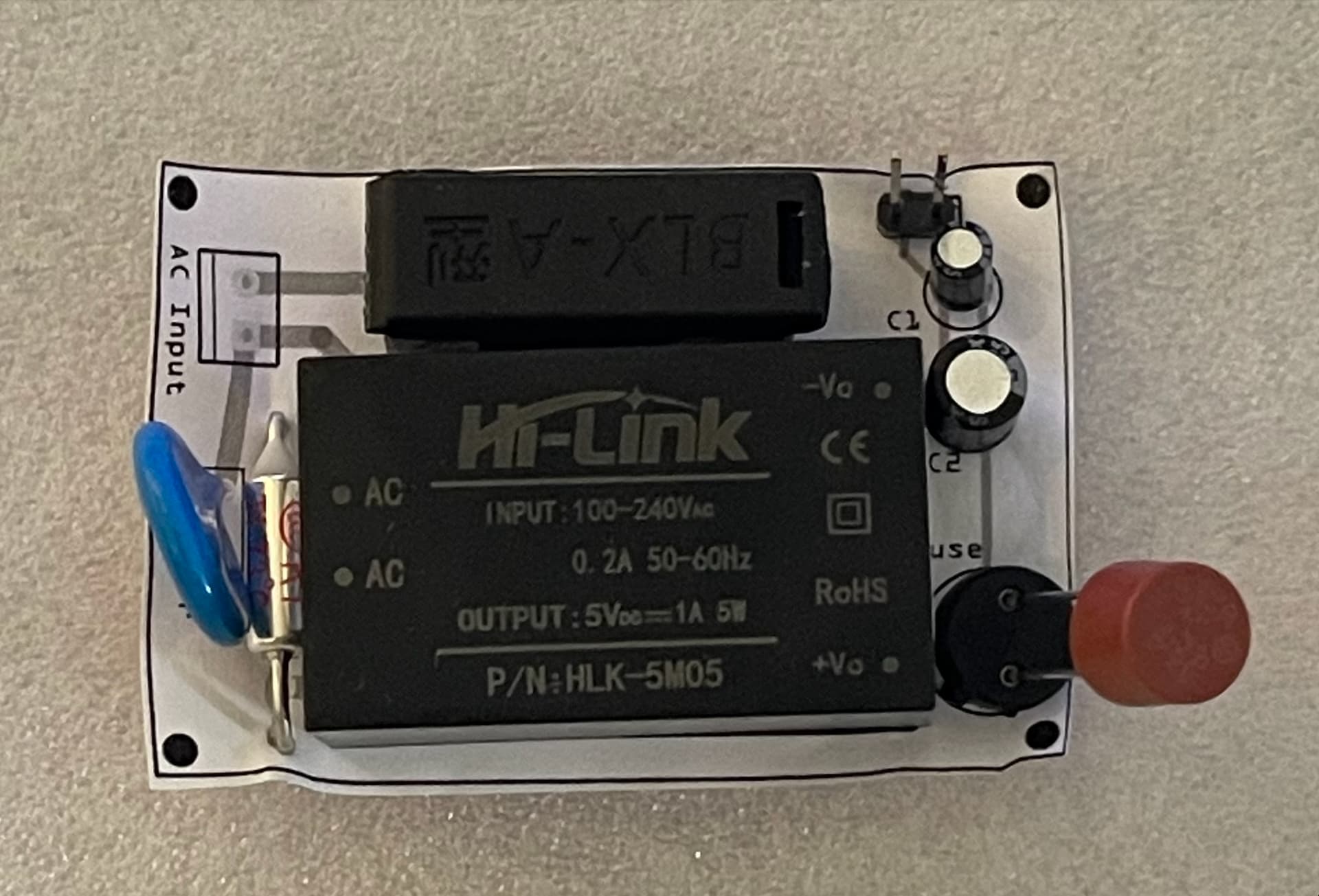
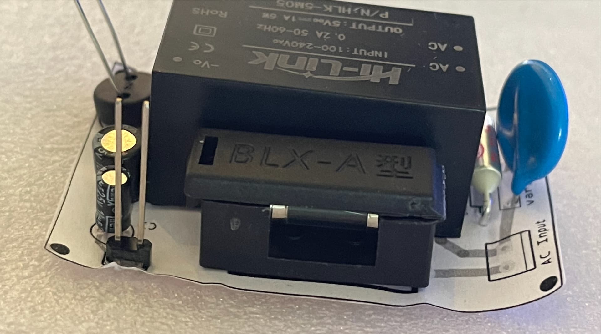
Here the parts received:
- Fuse holder TR5
- Fuse TR5: T1A
- Fuse glass tube holder
- Fuse glass tube : 0.2A
- Thermal fuse: 10A, 73C
- Aluminium electrolytic capacitor: 25V 100UF
- Aluminium electrolytic capacitor: 25V 10UF
- Varistor: 14D361K 360V
1 Like
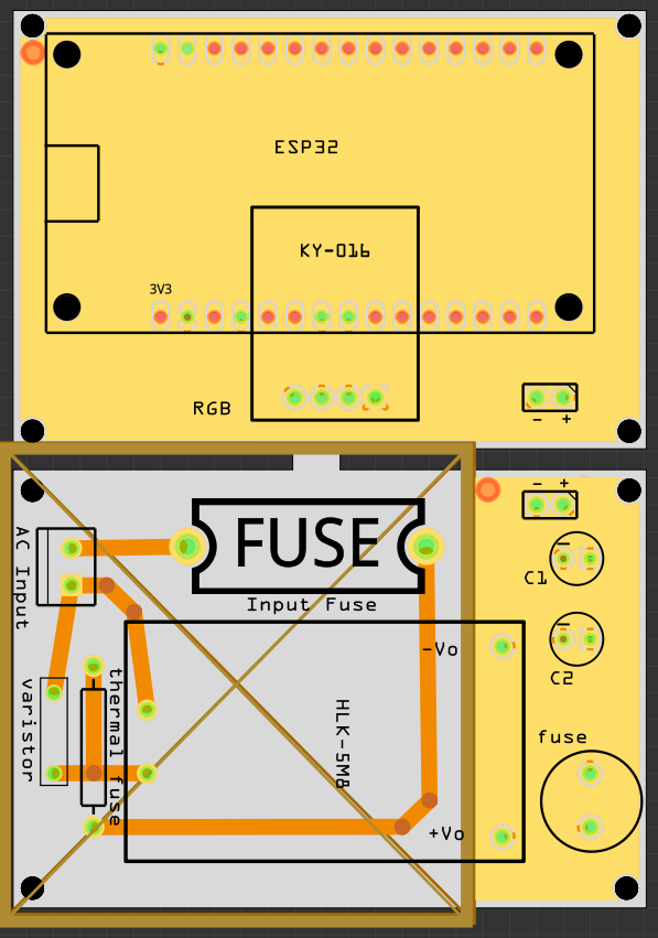
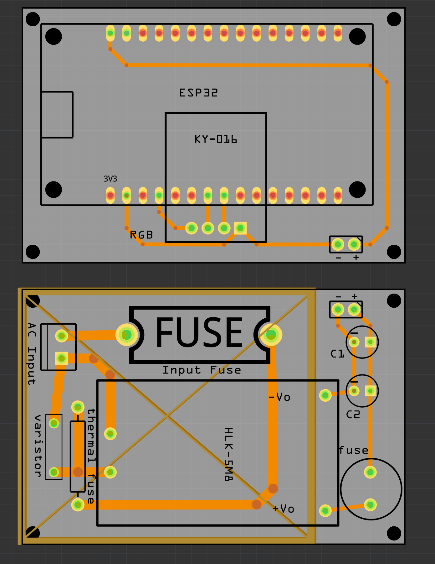
Assuming (which may not be correct!) that you intend to stack these two boards on top of each other the placement of the connectors circled in red appear to be incorrect. The connector on the top board is slightly further away from the edge of the board than the one on the bottom. If you put screws through the mounting holes the connectors likely won’t align between the boards (and the top board would have to flip vertically to mate with the connector on the bottom.)
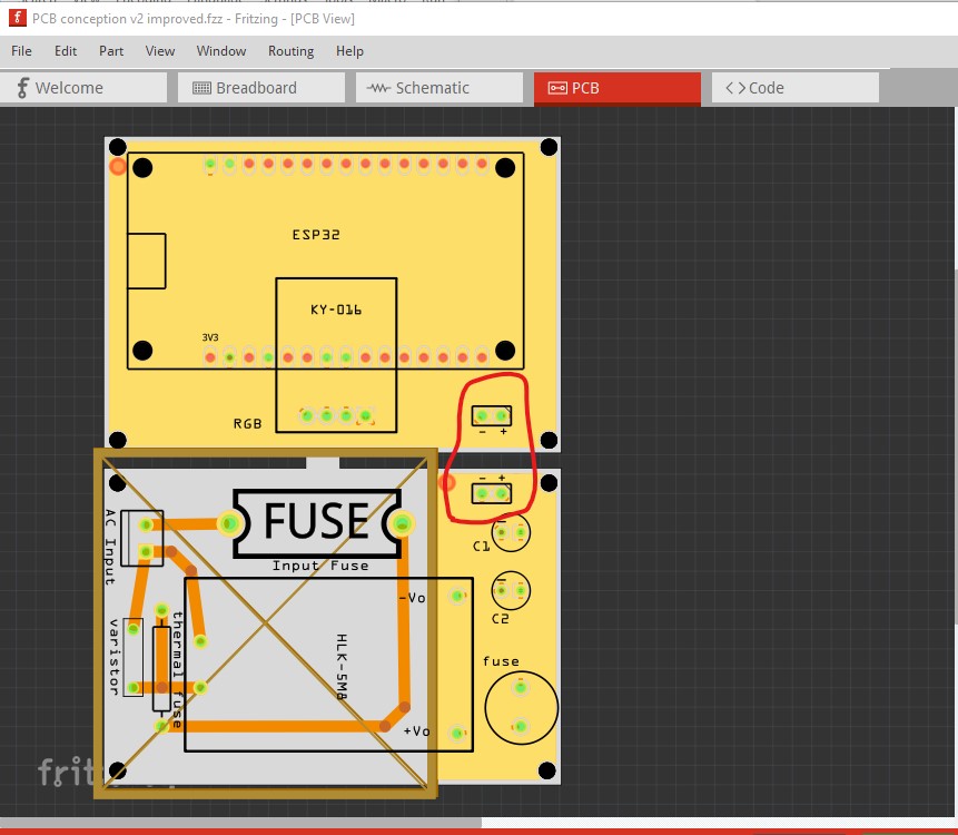
Peter
Thank you Peter,
I didn’t see it, I will update to have something align perfectly.
In theory selecting a part such as the jack should show you the x./y coords in Inspector, but copper fills appear to be breaking that.
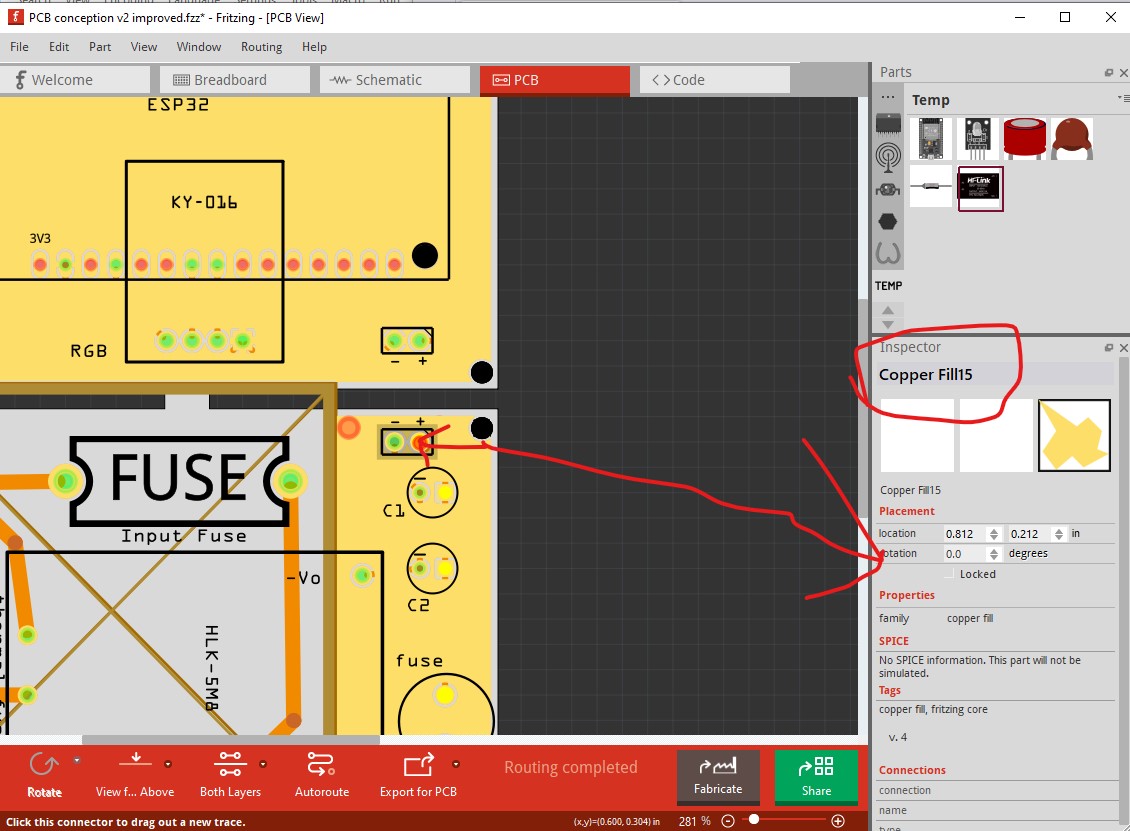
like this (here I suppressed both copper layers in views to block the copper fill)

The x/y coords in Inspector (circled in green) let you see / change the position of the part and should let you align them at the same distance from the mounting holes on both boards which should insure proper alignment.
edit
Looks like clicking on the silkscreen rather than the connector will select the part and let you move it.

Peter
Also make sure your screw connector does fit and can take a suitable cable. You only had allowed for a 3.5mm pin spacing version. Already the comparably bigger 5.08mm variant struggles with anything beyond a 1.5mm cable.