Hello,
Nicola from Italy here.Having read on the part creation section that is possible to ask for a specific part that doesn’t exist yet under a small payment…I post my request here hoping that’s alright.The part that i need is the df robot ph sensor featured in this page here https://www.dfrobot.com/product-1025.html for my graduation project so i would like to have it made properly.How does it work on the payment side?
@Old_Grey they accidentally have a few extra characters at the end of the link. I have corrected it for them.
I do have one of these sensors if we need dimensions. I would make the part but since they don’t likely want the PCB view but rather the breadboard view I am not likely the right person to make the part.
Ah! I was about to say it comes up for me now I see why. It looks easy enough there is a pdf of the board layout on the DFrobot site so breadboard shouldn’t be to bad. I’ll have a bash at it in a bit.
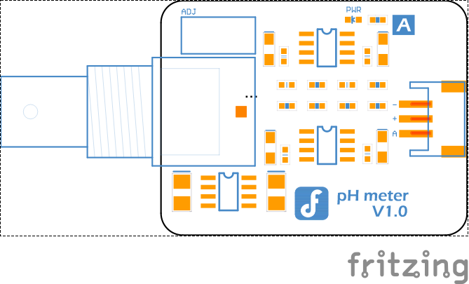
This part should do what you want. Download the .fzpz file and load it in to Fritzing and in your mine parts bin you should have a Fritzing part for the sensor. Breadboard isn’t quite accurate as the board is transparent, but it wasn’t created from the pdf as a path so I don’t know how to get a color fill in to it. Perhaps someone better at breadboard svg can figure a way to get the board background in. It should work fine as is, it just looks a little odd.
I haven’t opened the part but the reason I have had fill not work is because the area is made up of 2 paths. One on the outside of the line and one along the inside of the same line. To fix it you would select that element and then go to the path menu and select break apart (ctrl shift k). This will make two solid objects. One made using the outer path and one made of the inner path. Then you would delete one of them leaving a solid filled object.
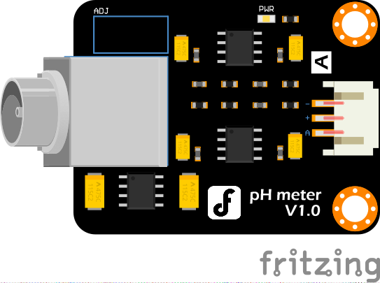
That did the job, thanks! I grabbed the bb image of a BNC connector from core parts, rescaled it a bit to match the space (the barrel isn’t long enough but close enough!) removed its connectors and pasted it in to bb giving this:
which with your background makes this about as good as it gets I think. This is the latest version of this part with the above change in it.
In this case the “board” is made up of 4 line paths (in a rectangle) and 4 arcs (the curved corner pieces), I expect @KingDarBoja did something similar to what you suggested to get them in to a single path that described the area so it could be filled. In any case, the final result looks pretty good .
I used node select and shift clicked each one by one, and then used Path Combine and it became 1 element in the XML dialogue. After that I couldn’t work out how to fill it and just got arcs in the corners. I’m hopeless at INK, but at least someone knows what they are doing.
I’ll try that out and see if I can master it. Once you have the path, the fill is easy, just select the path and then click on the color bar at the bottom of the screen for the color you want and it will fill (I think right click gets you a select of fill or stroke for the color) or select it and set the fill or stroke in xml editor whichever is easier for you. Working together we can do much better than working alone as this part shows. The final result is much better than my original and @KingDarBoja is much much better than I at making beautiful breadboard images than I will ever be (you need the touch of an artist which I don’t have). Hopefully we are all learning from each other and encouraging others to join in and learn too.
I did the same and got the same annoying result so I did another fix procedure: Dragged a selection box for each pair of path nodes then used the “Merge selected nodes”.
Okay, I will do the last fix to the breadboard view since I didn’t check the schematic neither pcb view because I hope you did them @vanepp.
Final fixes to the breadboard view: changed the resistor components to the ones from adafruit parts because look better for this board. Also added the trimmer potenciometer and removed the blue border lines.
That will be somewhat more difficult. There don’t appear to be any specs about size etc. around and it doesn’t have any connections that Fritzing needs (it connects to the interface board which connects to Fritzing). If you can get a jpg or png image of the sensor (there seem to be a few around on the net) it may be possible to convert the jpg or png to an svg and add it to breadboard but I at least have never had any success doing so. Alternately someone good at making graphic images (which again isn’t me ) may be able to create an svg that looks enough like the sensor from the images available to do what you need.
OK, here is @KingDarBoja 's part with a fairly crude sensor added to breadboard view based on the measurements he found (as usual I couldn’t get anything useful out of importing the png and resorted to making it out of rectangles).
First of all thank you very much!
But there’s a problem that i can’t solve…i’ve imported the file PH_meter.fzpz and now i can’t install the last .fzpz on this page because the program says “there’s already a part with ID… loaded into fritzing”…what can i do?
Solved! Thanks!
last question…have a look here…https://www.dfrobot.com/product-1025.html
the photo with the three components…the one with the three wires together (the blue,the black and the red) am i able to find it somewhere?
Help and thanks!
There likely isn’t a part like that available as it is an interconnecting cable with connectors on both ends. In Fritzing we would usually just connect wires to the board. Assuming you want it only in breadboard (with no connectors as it isn’t easy to connect them to anything) a custom part could be made by copying the connector from the board twice and putting wires of the correct colors between them. They won’t show in schematic or PCB as the connections are fairly difficult to do.
 now I see why. It looks easy enough there is a pdf of the board layout on the DFrobot site so breadboard shouldn’t be to bad. I’ll have a bash at it in a bit.