My name is Leo. I am part of a CANSAT team, and we decided to design our own PCB. If anyone could help me find a DF ROBOT BMP 388 symbol/footprint file that I could download to finish my schematics I would be very grateful.
Moreover, I also accept help with the kicad software, as I am a beginner.
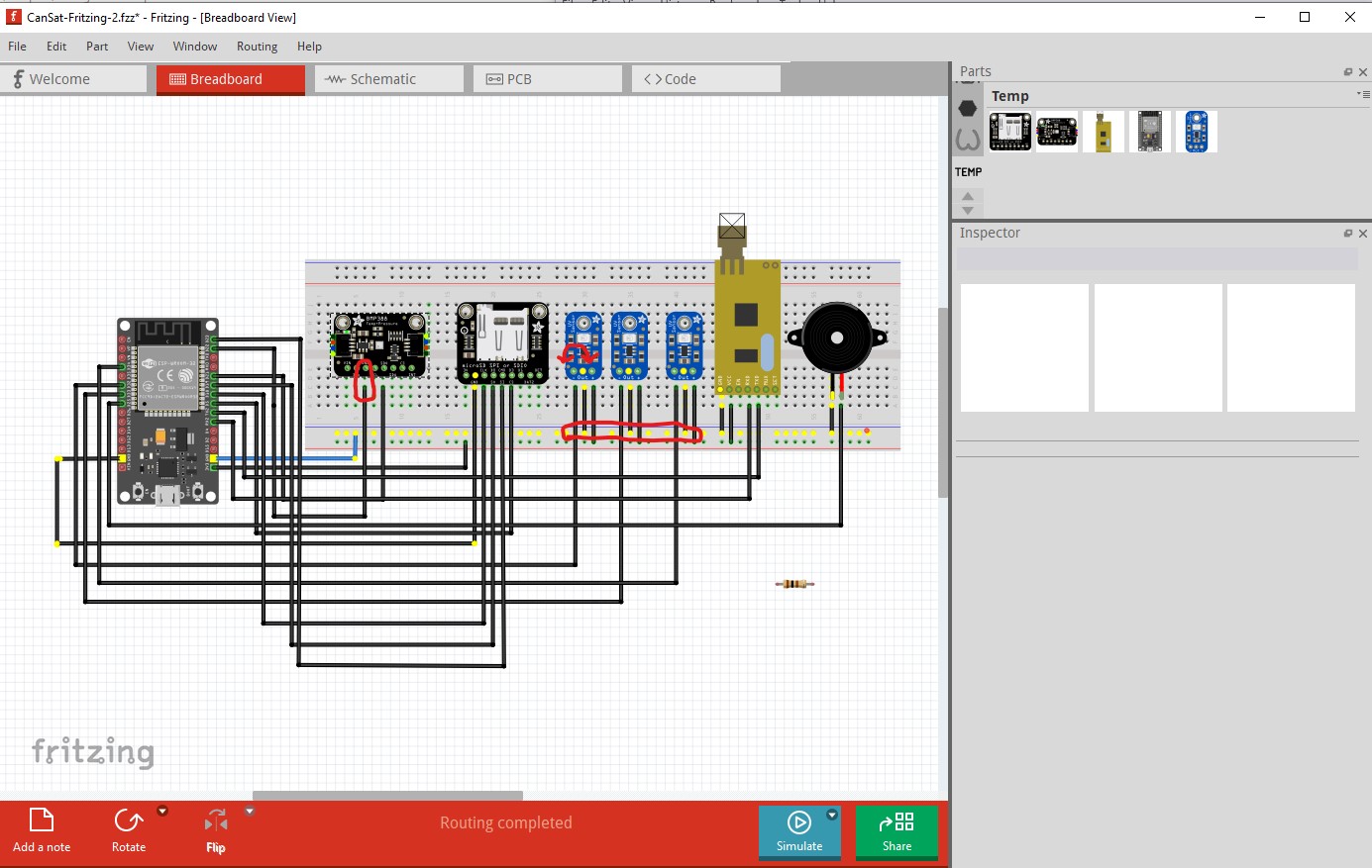
Your sketch is fairly broken. Here I right clicked on a ground line which will light all the ground connections yellow. The outputs of the UV sensors are all connected to ground and the ground is connected to the input pin (but without a ground won’t do anything at all.) The wires need to be reversed.
Changing to the 3.3V power bus we see the first two boards don’t have any power connections and thus won’t work. It is unclear to me what the current BMP388 wants power (possibly 5V?) on VIN with a 3.3V output on the 3V pin or 3.3V on the 3V pin. The DFR device will probably be different.
As well you need to check how much current your ESP board will provide. It may not have enough capacity to run all the modules (the SD module I think needs a fair amount of current and the ESP boards are usually low power) and you may need an external power source to power this. You should also route schematic as it would show you that you have no power to many of the modules and is a useful check for correct connections in breadboard.
@vanepp thank for your time. Well, its my first project, so rarely I know what I am doing ahaha however, I will add a 9v alkaline battery to the breadboard. The out should be connected to VP, and the (-) to the GRD right? CanSat-Fritzing- NOVO.fzz (114.5 KB)
Are u able to fix the main issues?
No VP is a GPIO pin the battery needs to go between ground and the VIN pin (battery negative to ground and battery+ to VIN which takes 4 to 12V.) Note the IO pins are not 5V tolerant so if any of your modules are running on 5V they will need level translators to interface to the ESP. I could fix the obvious errors, but you would be better off to do it yourself to learn how. Since I have no idea what this is intended to do I won’t be much help otherwise. The reference for the board that I found doesn’t indicate how much current the 3.3V regulator can supply to the outside modules so you may need a buck regulator module to provide 3.3V to the modules (rather than from the cpu board) but I have no way to tell. You will also need to wait for @RAPTOR7762 to make the DFR BMP388 part before getting much further. The APC220 radio module appears to be able to run on 3.3V so it should be OK (it only appears to take about 30ma)
okok. I was talking about the uv sensor when I said the OUT should be connected to the VP. The pins work on 3.3 v, but thanks. We are lauching a satelite and want to gather temp, press, altitude and uv radiation data using I2C
Yes the ground and out pins on the 3 uv sensors need to be swapped (out to gnd and gnd to out) although none of them currently go to the VP pin. While I know little of satelites they typically need both radiation tolorant ICs and low weight (which breakout boards don’t provide. You would typically be better to make a pcb with the chips in the UV sensor to avoid the extra weight of the breakout boards. It is a very specialized field.
OK here is a bmp388 part. @AnnePloir you may want to consider this instead of the IC you requested. Note the documentation on the DFR wiki is wrong (the dimension image is an apparent old version of the board) so this part was made from the jpeg image. As a result the pcb footprint may not be accurate. Before ordering boards print the pcb footprint out at 1:1 scale and compare it to a real board. As well the mounting holes as usual are not drilled by default. If you want the mounting holes you need to drag a hole part from core parts pcb in to your sketch, place it over the image in silkscreen and set the size appropriately.