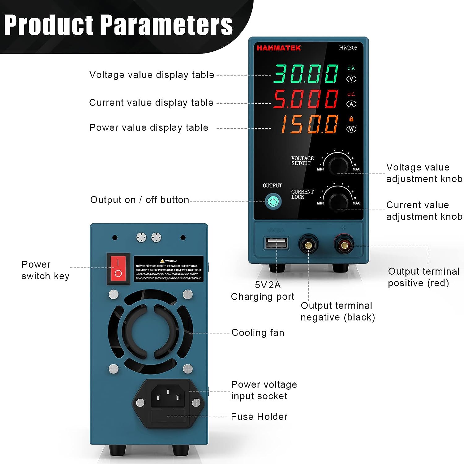
I want something like the following picture:
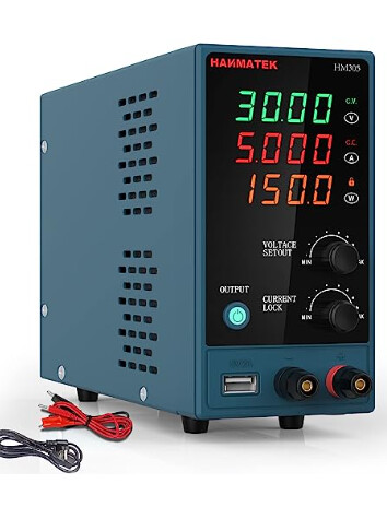
It doesn’t need to be exactly the same, I just want to show people I’m using a DC power supply, not batteries, etc.
I have been thinking about creating this kind of part for some time and it is in my TODO list, but it will take me some weeks.
@vanepp , if you make this part could you create it similar to the multimeter, with two knobs for adjusting the voltage (coarse and fine-tune) , another two for the max current and the CV and CC indications? The screens for numbers should be without numbers as the multimeter. Thus, users could add a text logo for their images, and in the future I will add them through the simulator code (or a special class of item in the long term).
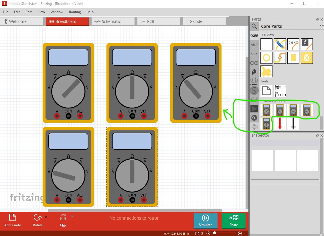
I can do that, but am I missing something? I don’t see two knobs on the multimeters in measuring tools. What kind of connector definition do they need in the part to interface to the sim code? Is there another multimeter I have missed somewhere? I haven’t tried the simulator yet so may be missing something!
Peter
There are generic power supplies available (but not in core parts because I have been lazy!) It is however quite a bit simpler than this unit (there are three of these for different versions that people have requested)
this one is generic-ac-power-supply.fzpz there are also
generic-ac-power-supply-2.fzpz
and
generic-ac-power-supply-3.fzpz
which a search in the forum search bar should find as the parts were posted to parts submit. I’m open to making a unit like this when I figure out what @fai needs in terms of the simulator (since I can probably make the part much easier than him.) Since you asked for it you are likely to get your image ![]() .
.
Peter
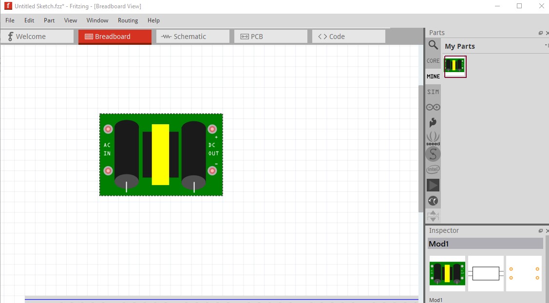
OK here is a part for the power supply. It doesn’t quite meet @fai 's request as it doesn’t have the requested coarse / fine knobs at present. They are easy enough to add to the interior of the current adjustment knobs once I know what they need to look like. I got somewhat distracted by finding a number of bugs I need to report in breadboard (the breadboard which I use fairly rarely is screwing up in a variety of ways) which slowed testing of the part.
hanmatek-HM305.fzpz (5.2 KB)
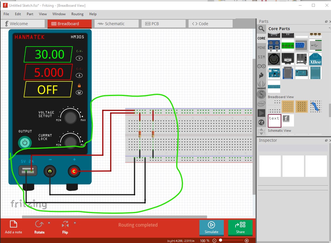
This part looks like this (after the breadboard bugs were eliminated!)
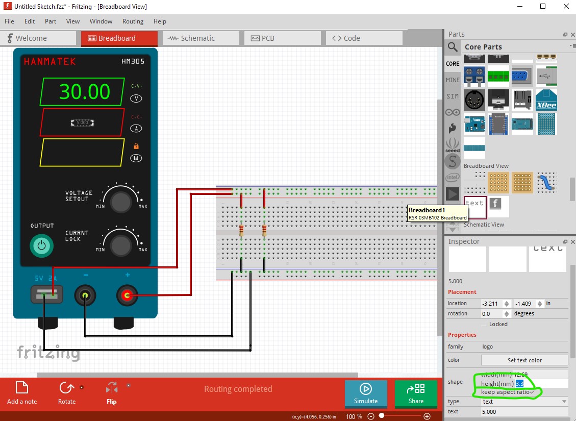
as requested the screen is initially blank (so the simulator can later write text to there) so yo need to drag a text box from core parts in to breadboard, set the text to what you want then change the size and color of the text to match the real unit which looks like this
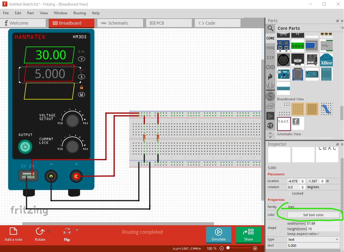
changing the height to 15mm (with the preserve aspect ratio box checked which it is by default) sets the correct (of not slanted like the real device) value.
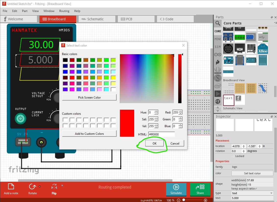
click on the set color tab in Inspector (the lower right and window) and select your color (I put a box that doesn’t appear on the real device around the 3 text areas to give you an outline for where to put the text. Then hook up wires to the 4 connections (the USB charger port and the actual supply output)
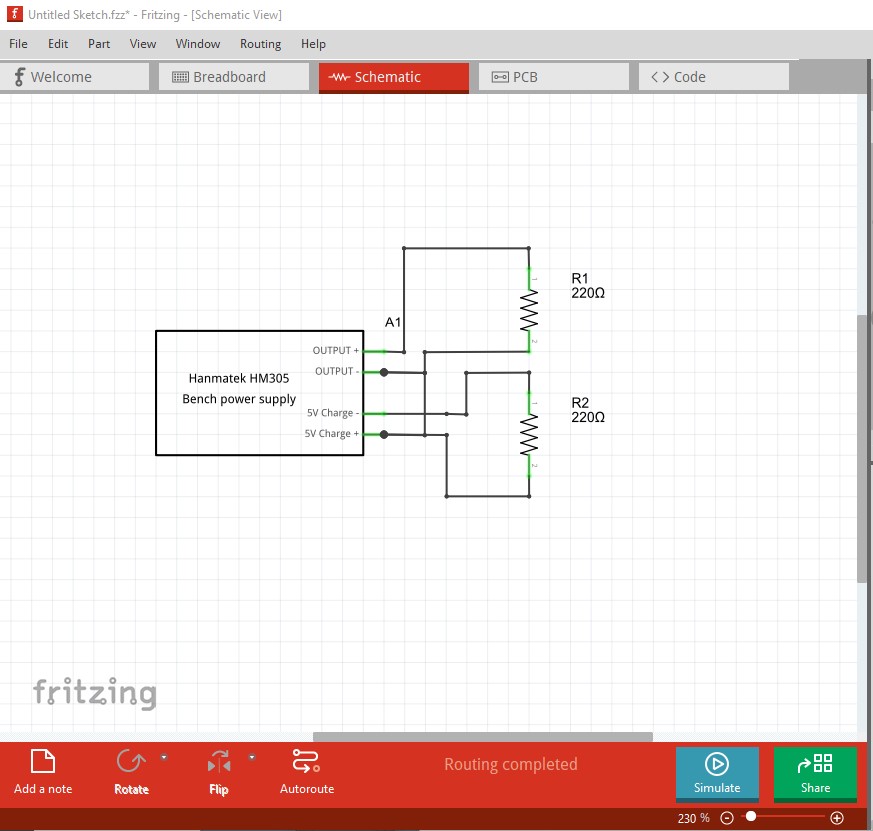
schematic (once routed) looks like this
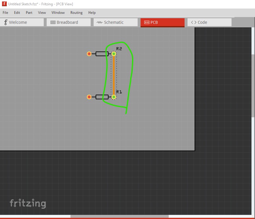
and pcb has the power supply suppressed as it can’t be easily (or at all really) installed on the pcb, but the resistors and their ground connection do show up.
Peter
1 Like
That part looks very good!
What in meant with “similar to the multimeter” was that the feel and look alike be some what similar to the multimeter and oscilloscope parts. This is not a requirement, I was thinking that it would be nicer if the parts in the core look homogeneous. We can also change them at a later times, but the obsolete process is painful.
In any case, the part that you made it really nice, but in world change a few things:
- For the core part, I would remove the branch name.
- I would remove the USB port and leave it as a single power supply. We could also make a dual power supply (2 independent and adjustable power supplies with two screens or just adding a fixed 5V 2A power supply but with borne connectors)
- The sch symbol should be a DC power supply. Two of them in case of dual power supplies.
- not sure about excluding it from the PCB. Batteries usually have a 2 way 0.1in pitch connector.
- it would be also great if the elements (CC, CV text elements, buttons and knobs) have human readable ids. In the future, the similar could change its properties depending on the output of the simulation.
- maybe I write just voltage and current for the text of the knobs
No worries about adding a coarse and fine tune knobs. I think I could work something in the code and use only one knob for each property.
Thank you!
What a great job!
I really like that power supply.
1 Like
after downloading the part that you made, how do i get it into the program to use it?
Either double click on the .fzpz file which will load it, or File>Open->file name which will also load it.
Peter
1 Like
Or drag and drop into a Fritzing window.
1 Like
thank you very much for your help. is a great power supply.
How i can use it in Simulation to take the Power to the Breadboard?
You need to find a part that has spice data. This one doesn’t. There may be one in the simulator parts. @fai would be the person that would know if there is one yet (it was planned when I made the part, but may not yet have been implemented.)
Peter
Hi,
I made some adjustments in the power supply and it is available in Fritzing (search for “lab power supply”). It has SPICE info, but it will not simulate as we have a packing error in the official release (a code model needed to simulate the part is not found). I hope that this will be fixed in 1.0.5 and add it to the SIM bin. Maybe @KjellM can tell you more about the status of this in the next release.
The developers pay less attention to the forum (but a lot more to the fritzing-app GitHub repository!)
You can make an enhancement request on GitHub
Hello, can someone tell me how to turn on the power supply? I’ve gone round and round and I can’t turn it on, thank you.
Other than in simulation (and I am not sure it has a spice model yet) it won’t “turn on”. It is only a power supply part it doesn’t turn on.
Peter