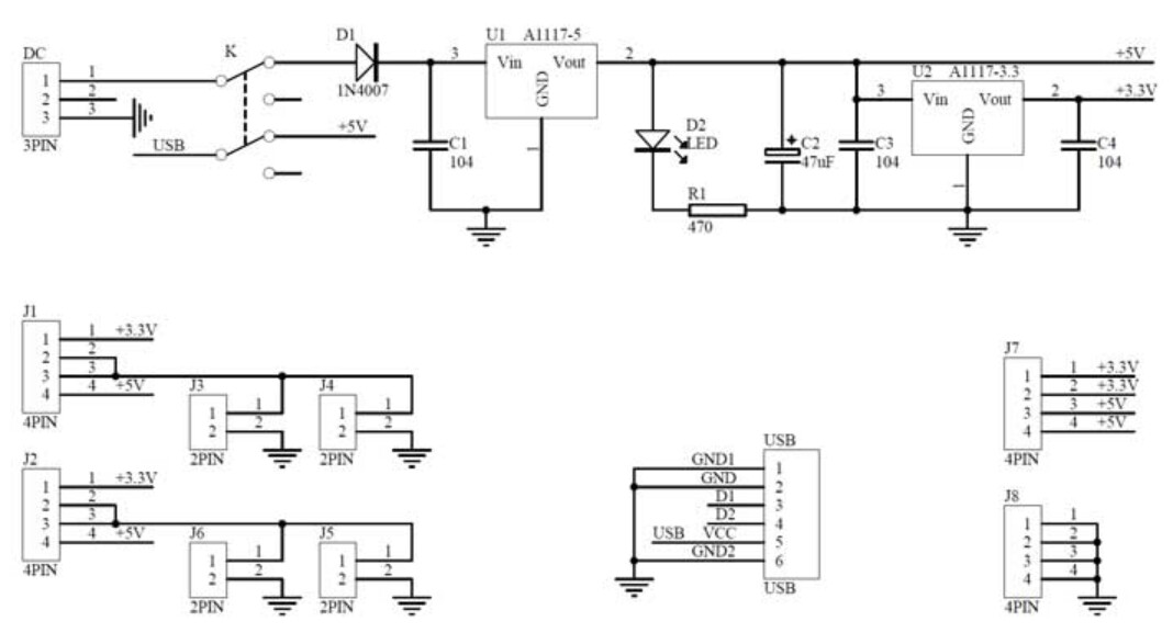
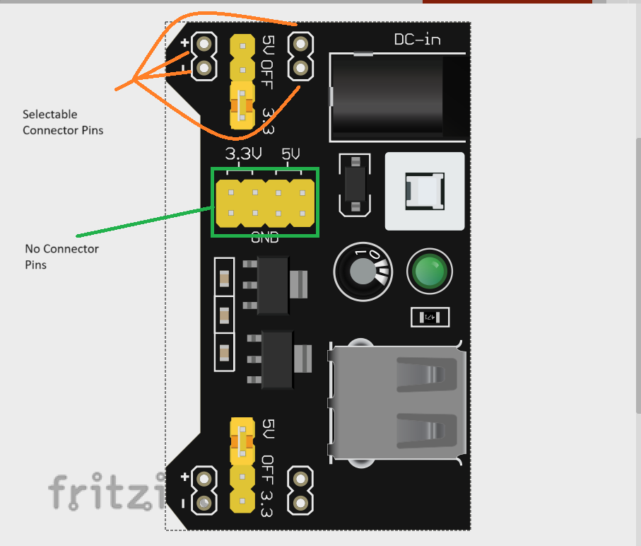
It is a simple DC power supply chip, but the center section with the 2x4 male pins sticking out have no connectors and the schematic doesn’t reflect the real chip. I believe this is the Schematic diagram:
Just as with the one I uploaded, connector pins are only available on the sides, but the above labeled junction is where I need there to be connector pins. On the real part, they are male pins.
Looks like it is more complex than I expected. I have a fixed part but it doesn’t render correctly and I so far can’t figure out why (possibly a Fritzing bug which I may need to get developer help with if I can’t figure it out, which may take a while as the developers are busy!)
Found (if not completely) my error, it appears to be a family name issue although I’m unclear why, as the family name doesn’t appear to be in use. I’ll file a bug report on the issue on github. I corrected that and this part should do what you want. Note only the bottom pins that are intended to connect to the breadboard appear in pcb. The rest are intended for jumpers and won’t connect to the pcb.