Welcome to parts creation hell  , sounds like you have already been bitten by the monsters but prevailed, hope you continue creating parts. That said there are some problems (none terribly serious):
-
Both parts have the same moduleid so you can only load one or the other. To fix, edit one with parts editor, save as a new part (which creates a new moduleid) and export it, then copy your svg files over the ones fritzing created (except for the fpz which you need to edit to make the changes to the metadata if you don’t do that in parts editor).
-
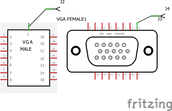
The schematic svg is missing the terminal defiinitions (they are in the fpz) which causes this:

note on your original the line terminates in the center of the pin. Setting a terminalid to the end of the line terminates it on the end as is desirable. -
The pcb has copper rings around the mounting holes (which perhaps you wanted for some reason?) and the hole is .128in rather than .125 (1/4) which the data sheet calls for (found in the gerber drill output). The pin holes will work for this particular connector, but there is an Amp one (data sheet here)
which is the largest of those on digikey at 3/64s so I increased the hole size to 0.046837 to fit that or any of the smaller ones (the footprints are otherwise standard). As well there was no silkscreen so I added the outline of the part to silkscreen to aid in component placement on the pcb (this part sticks out a lot further than the pins indicate).
I fixed all of these and did a bunch of internal cleanup (this was based on an older part and still had separate copper0 and copper1, and fritzing export’s usual deep levels of group nesting) and added a better (if not by much  ) breadboard view, although I agree probably not many will use it. Note the new breadboard svg uses bendable legs, so parts editor (and modifying it with Inkscape unless you post process it to remove the style commands which I did) will break it. If you have questions about it feel free to ask, always glad to encourage parts creation. My updated versions:
edit: just realized schematic on the male is wrong, will correct it and repost. This one should be correct (if you have downloaded before seeing this comment. please redownload!). Well not quite, breadboard is incorrect as well. Sigh, third time lucky. After a good bit of scratching my head (and finally resorting to getting an old vga card with a physicalconnector to trace  ) I think these two do it. I added the type on the silkscreen as the pin outs are different.
DB15 VGA female fixed.fzpz (24.4 KB)
DB15 VGA male fixed.fzpz (28.1 KB)
Peter