I am making a design with a small custom QFN part. But when it is exported to a Gerber viewer, the solder masks are too large, leaving no room between the pin pads which will make soldering troublesome. Is there any way/setting/workaround/shortcut to deal with it? Thanks.
We had this discussion before but couldn’t find anything to change the mask. I had ideas but didn’t try anything.
If you want to do experiments with the above info and find a solution please post it.
After paying a visit to the source code and doing some experiments, I am convinced that I have resolved my issue by setting the svg “stroke-width” attribute to “-0.5”. But such workaround does come with a display problem in the PCB view in Fritzing.
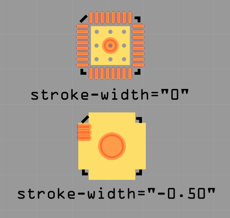
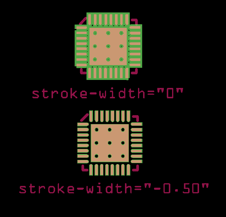
Is that changing the stroke-width of the contacts in the copper group?
Yes, that’s right. Though this attribute does not accept negative values by the SVG standard, it just works.
@qazwsxedcrfv000, I take it that you want the solder mask between the pads but don’t want to change the width of the solder pads… is that correct? You want the solder mask to come right to the edge of the pads?
Yes. I want to adjust the solder masks without adjusting the copper layer so that I can follow the design recommendation from the IC maker and make my life easier by reducing solder shorts or bridges on QFN parts… In this case I want to have a margin of ~0.07mm between the copper pad the solder mask window.
The solder mask margin in Fz is about 0.1mm. I take it that the solder mask window is about 0.1mm±. I guess Fz needs to have a way to address this issue… There is a way to do it… it takes a little creativity. If you would like me to show you a work-around, post the .fzpz and a link to the data sheet and I will work on it…
Update:
Fz originally was going to include defining solder-mask in a layer in the pcb.svg… http://fritzing.org/forum/thread/2312/
Fz is supposed to automatically expand the solder-mask border by 6mil, 3mil (0.0762mm) around the pads, http://fritzing.org/forum/thread/1125/. Although, I don’t see that unless it does not show up in the Gerber test. I ran three different Gerber test programs and none of them showed a solder-mask window between the QFN, 0.215mm spaced solder pads. One of the test produced an .svg… the solder-mask border measured out at about 0.125mm.
I created a QFN with 0.5mm pin spacing and 0.15mm solder pads… the spacing between the solder-mask keepout from the Gerber test, solder-mask. svg measured about 0.1mm (0.125mm solder-mask border). A QFN with 0,5mm pin spacing and 0.285mm solder pads showed a total blackout for the solder-mask. Again, I set the solder pad width to 0.13mm and measured a solder-mask window of about 0.12mm. So all test show, if the Gerber test .svg is correct… Fz has a solder mask border of about 0.125mm and not 0.0762mm… Oh-Oh… did I fine a bug…
Quick Fix: Create 2 sets of Gerbers… One normal set and a second set with the QFN solder pads set to a width of about 0.13mm or whatever you prefer… then pull the solder-maskTop.gts from the second Gerber set and place it in the normal set of Gerbers.
I am not really a C++ programmer per se but I think I can still understand its codes.
In gerbergenerator.cpp line 61,
const double GerberGenerator::MaskClearanceMils = 5;
And in svg2gerber.cpp line 34,
static const double MaskClearance = 0.005; // 5 mils clearance
I suppose these mean the clearance is set to 5 Mils, i.e. 0.127mm which is in line with your test results…
I was right in the middle of reading your post when you withdraw it… I didn’t understand a word you said anyway…
I kind of thought the solder-mask border may have been set to 5 mils instead of 3… It appears you found the source of the problem… Have you tried to change it to 3 mils to see what happens?
Apparently they changed it to 5 mils or some reason or another…
I have discovered some lines that are at odd with my own workaround results… I am unsure how come my workaround works at all now… That’s why I have that post withdrawn. I am sorry for any inconvenience caused. 
I think I really need to clone its source code and setup the proper toolchain to give it a closer look…
This is way over my head… I would think that if it is suppose to be 3 mils instead of 5… then this should be corrected on the next release  I would think 5 mil would be fine for most parts but not for the QFNs and other little bitty buggers… If they leave it at 5 mils then there should be an override… although, I suppose that would just complicate the code…