I’m looking at starting a project in which the PCB would be in the shape of a “C” and could be as large as 12" x 12".
Is there a way to create a breadboard and PCB in those size and shape?
The project would have no more that numerous lights on it, which would light up in sequence and/or all together. Would like to use Fritzing if possible.
You can design your own custom pcb shapes and load the image into Fritzing… see, http://fritzing.org/pcb-custom-shape/ . Although the instructions are not quite up to date. You need three layers; board, silkscreen, and silkscreen0. silkscreen0 is the bottom layer and can be the same as silkscreen. The ID attribute of the board images itself needs be be named “boardoutline”
Thanks again, I was able to fumble my way around and produce a svg. Was then able to open it in the PCB tab using your instructions. Size is way too big, saw the price to build, yicks. Will have to be make it smaller.
Everything in PCB view has to be dimensionally accurate because it is for production, the other views aren’t that critical but it’s good to work on a 0.100" thou grid so things line up with the breadboard, if it’s used. Select units in preferences that you will use, you will probably have to select those units in other places to, and it should be right.
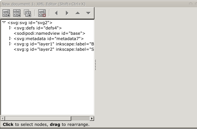
There seams to be a XML structure - critical in PCB -. You can raise and lower nodes, indent and unindent them, in fact that’s how I do my XML rather than coding it directly.
Thanks Old_Grey. I’ve played with the image in Inkscape, imported into Fritzing and played some more. I now have an idea out to get things from an image to a PCB.