I am modifying a breadboard part which has pins at exactly 0.1 inches apart. When looking at Inkscape with Grid on set to 0.1 inches, all the pins are exactly at the intersections. However, when I use add the completed part to a project, the pins line up perfectly in the X direction but are exactly 0.05 inches (1/2 a hole width) off in the Y axis.
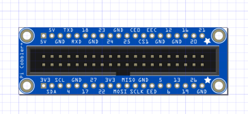
Image taken from Fritzing … notice that the pin holes are NOT on the grid markers.
When I try and drag the part (the header) downwards in FZ, it seems to want to move in 1 grid square (0.1") units. So when I drag it down … even by the smallest amount, it seems to jump a whole grid square and I am no better off. I can’t seem to move it a fraction of a square. I’m at a loss to explain, the part just seems to be “off” by 1/2. I should have mentioned that the part (exhibiting the problem) is available on github here … if you’d like to try it yourself and see if you see the same results, that would be fantastic…
Thank you sir. That is most certainly a valuable workaround. I thought I understood how parts were made in FZ but this one is most mysterious to me. I had assumed that since everything lined up in the Inkscape model, it would do the same in the breadboard view … so the underlying cause (to me) is still a mystery … however your tips have got me past where I was … TY again.