Hello, I am pretty beginner and I need some help please. I was trying to create a 6xAA fritzing part for learning the basics, but I am encountering mainly a Breadboard view and PCB view issues. I will describe a little bit the steps I have done because I am not pretty sure if I have followed a good method neither good practices. I have followed some tutorials from the fritzing and some tutorials from some blogs.
Firstly, I have started my part from the “Battery” “Your standard 2x AA battery pack (3 Volts)” which I don’t know how to add the .fzpz here. It can be found at Core Parts → Power (I think).
But this is the Breadboard original svg: (I add at the end of all svg files the “.fzpz” because I read somewhere that forum can not deal good with .svg)

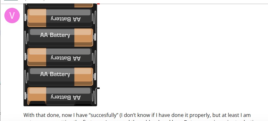
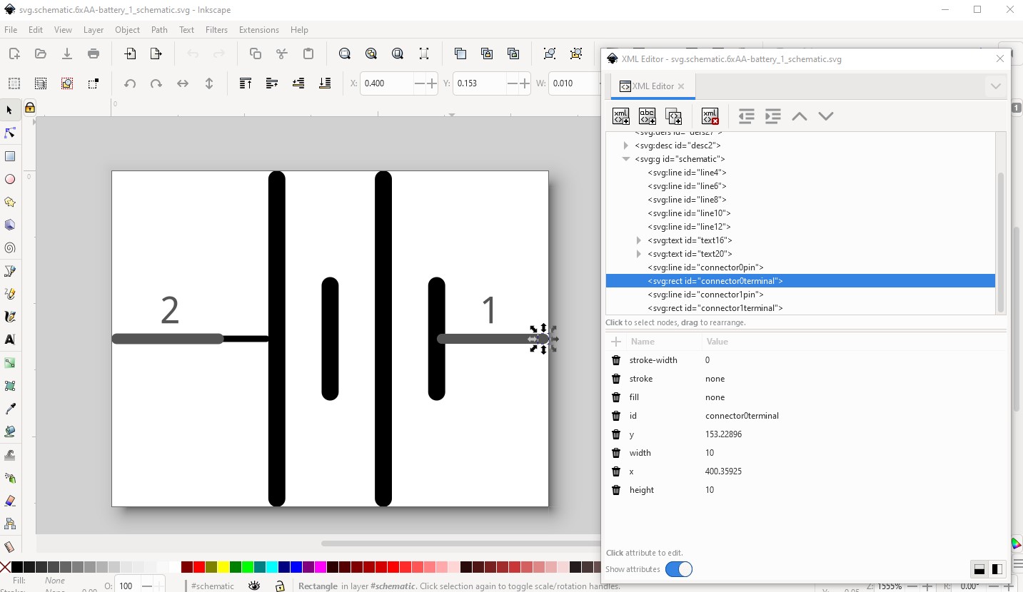
The next thing I have done is with Inkscape edit the 2x AA battery svg and I have converted into a 6xAA battery svg for breadboard (I think I have not used too many good practices for doing it).
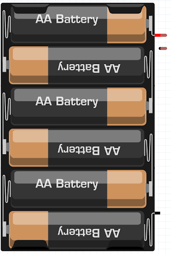
This is how it firstly seemed to look:

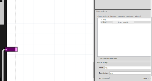
Here is where I have the first problem, the original part is odd and is using rubber band legs (as well refereed as bendable legs):
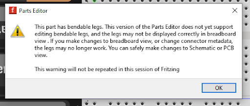
I did not want them because of personal criteria and because if I used them, the fritzing part would look like this at the breadboard view:
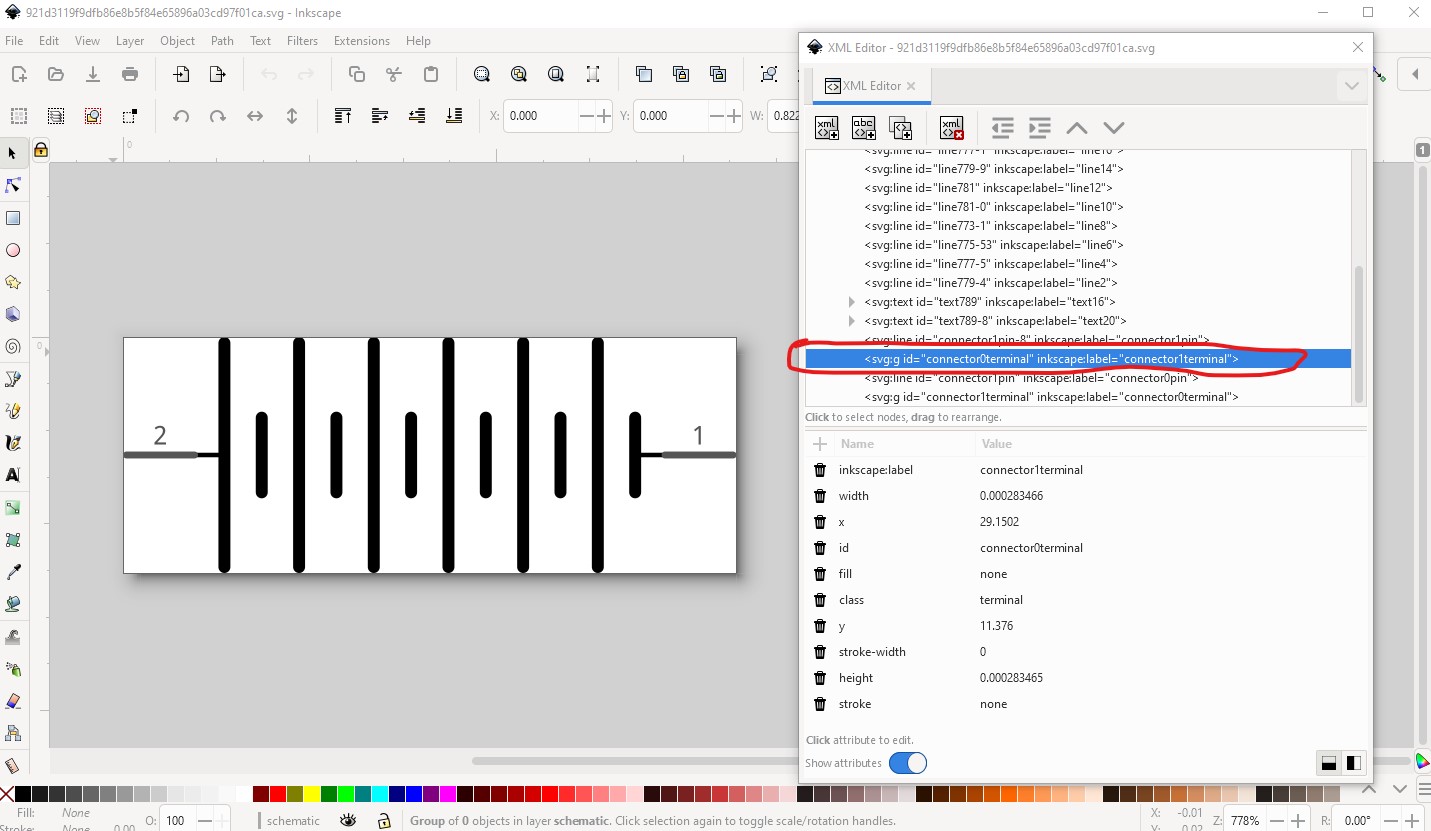
So I have edited some hierarchy with Inkscape (I think I have not used the hierarchy pretty good) and I have as well edited the xml file with VSCode and commented the parts that I think are the band legs:

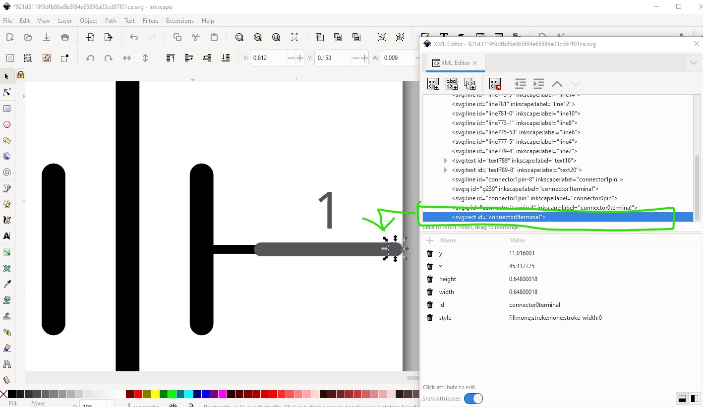
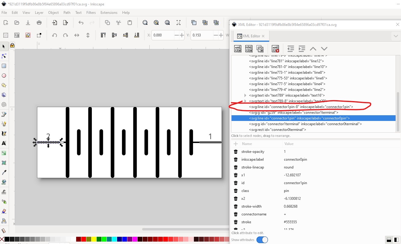
With that done, now I have “succesfully” (I don’t know if I have done it properly, but at least I am not anymore getting the first error) removed the rubber band legs. But now my issue is at selecting the graphic, fritzing selects the following:
First Issue:
At this point I think I had been able to design the 6xAA svg even though I might have used bad practices (which I am not capable to notice due to that I am pretty beginner). But for making the part I would prefer that the graphic was just the black pin, in the case of the image and the red pin and I don’t know how to do it. I have searched information if this could be related to the bendable legs, but I have not found anything that helped me.
After that, I knew that I had to make a svg view for the schematic and PCB views. And with the PCB view is where I have my other main issue. I have as well used the svg of the PCB view of the same original part “Battery” “Your standard 2x AA battery pack (3 Volts)”:
![]()
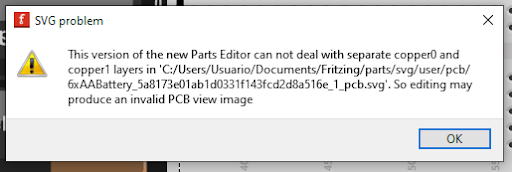
Second Issue:
By doing that now I get the following error:
By changing some hierarchy using Inkscape I managed to get rid of the error, but I don’t know if it is a good thing. How could I do it in a more properly way?
PCB SVG with changed hierarchy and not getting the error:
![]()
(for the hierarchy I mainly used this structure: Fritzing Blog)
Summary: My mainly problem is how to remove rubber band legs and make the graphic good look, how to unbroke PCB view proper way and finally that I have a problem with good practices that I would really appreciate if I get some explained to me please.
PD: I don't know if I am adding in a good way the files, so you could be able to download them and check the xml code, if not please could you let me know?