I has some PCBs fabricated. When I tested them, I discovered that two grounds were missing on the layout. I added them on the schematic and layout. Fine, no functional probem. Weirdly, this created a strange wire between a spot on the microcontroller (no connection there) and a “random” point on the breadboard. I have a good layout so I shoud be happy, but I would like to get rind of this strange wire on the layout. I also would like to know if I did something wrrong or this is a bug. Maybe a little of both? Thoughts? This is my AI fortune teller project.
P.S. I am not going to get the boards re-made for two ground jumpers!
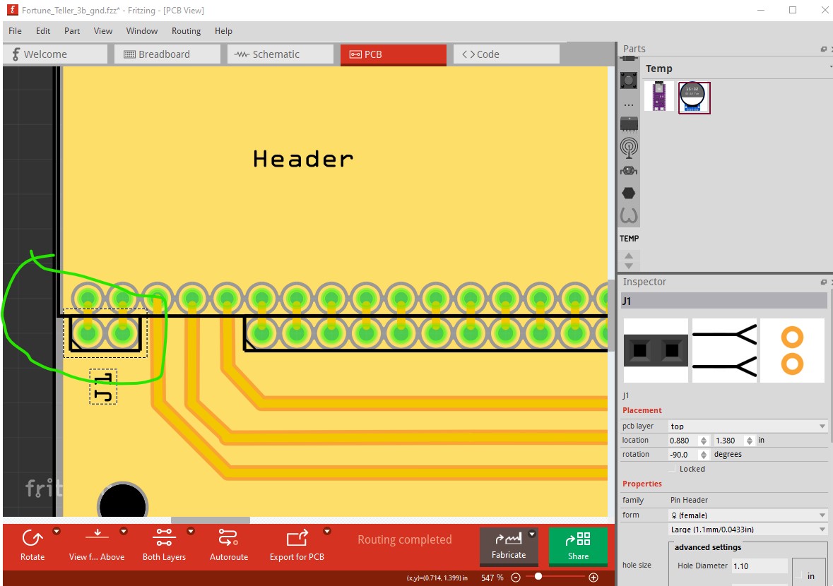
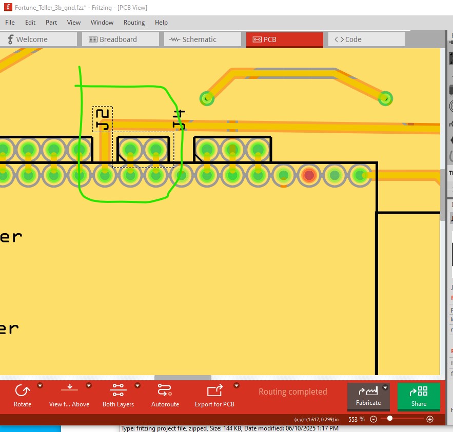
It isn’t clear what is happening but breadboard and schematic are not complete. These two ground connections in pcb are not wired in schematic and breadboard and therefore show rats nest lines where there should be a connection.
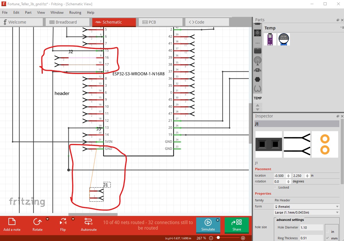
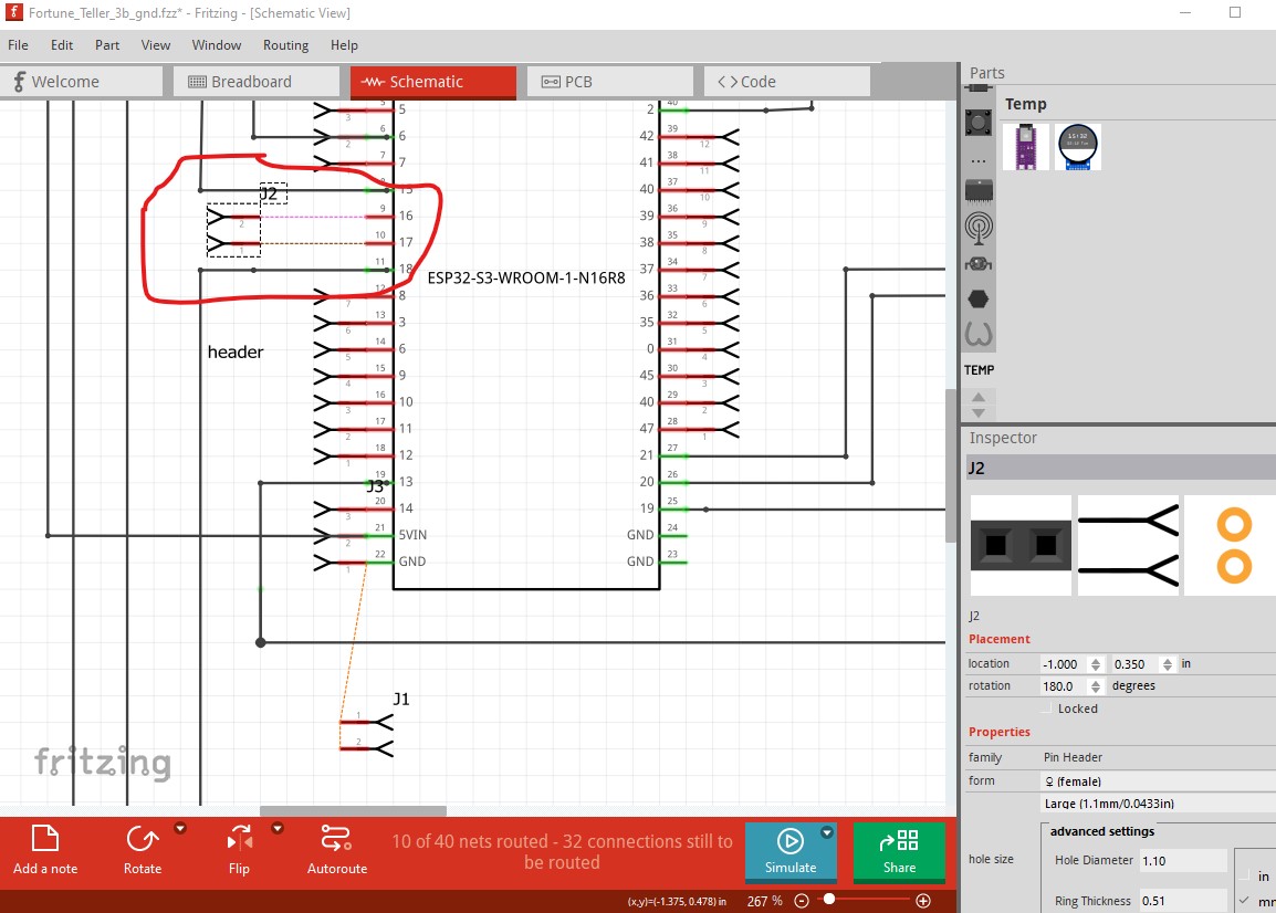
In schematic the rats nest lines (circled in red here) show a connection in pcb that is not routed in schematic. Routing the two of them makes that go away.
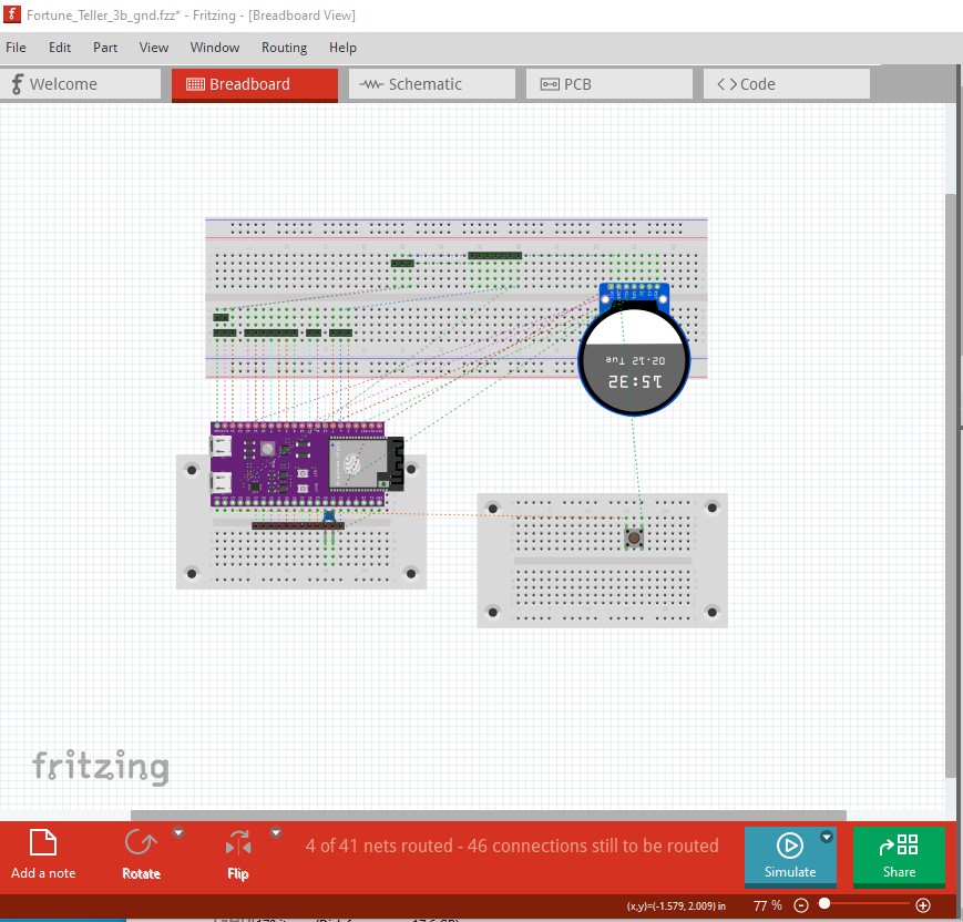
With all visible rats nest lines routed there is still an unrouted connection in breadboard (perhaps between the overlapped breadboards?) that I can see or there may be a bug. Moving the wiring around in breadboard may discover where the missing connection is. Clicking on the message circled in blue should highlight the unrouted connection in yellow but it doesn’t seem to do so which may be a bug of bad eyes on my part.
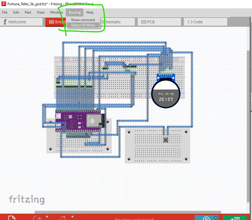
edit: It appears to be something you did, I’m not sure exactly what that was but this works. Do a routing select all traces, then hit the delete key on the keyboard to delete them all.
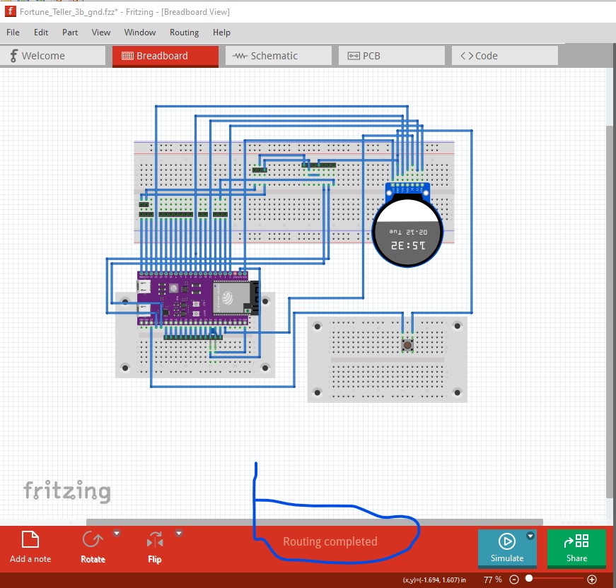
That gives you a clean breadboard with only rats nest lines. Now route the wires one at a time by clicking and dragging them to a sensible location and breadboard routes correctly.
I didn’t keep it but you can recreate it by deleting all traces and routing using the rats nest lines in breadboard easily enough. You are best to route with one wire to a breadboard contact (typically not to the part it self, although that will work in Fritzing just not real life) as I suspect one of those connections is the source of your problems. As well if you right click the mouse while hovering over a pin, all connections in that net will highlight in yellow showing you what is and is not connected (if the connection doesn’t light yellow or is red, not green, then it is not connected!)