Hi,
New to Fritzing, but have successfully created a board.
However, I want to modify some existing parts using InkScape. But for some reason the image for PCB-view of the part is not saving in InkScape as expected. (BB and schematic views are OK).
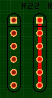
See image below from PCB-viiew in Fritzing.
This example is the resistorpack in the core-bin. Five resistors in the same package.
The left part is the original PCB-image, it’s OK. The right part is after opening the image in InkScape and just saving it again.
There’s a thick red line in the image saved with InkScape
Same problem with all parts I have tested.
SVG-Images extracted from the original parts fzp-file. No problem there.
InkScape 0.92 Fritzing 0.9.3b
Image saved as plain SVG in InkScape…
In InkScape it looks OK. But In Fritzing PCB-view there is this extra red line.
And also it’s not possible to move the part in Fritzing.
No matter where you click in the image, you only start a new wire.
Connectors looks OK when viewing images in Fritzing.
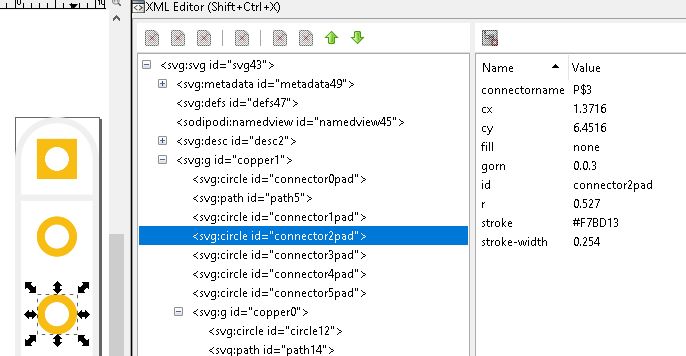
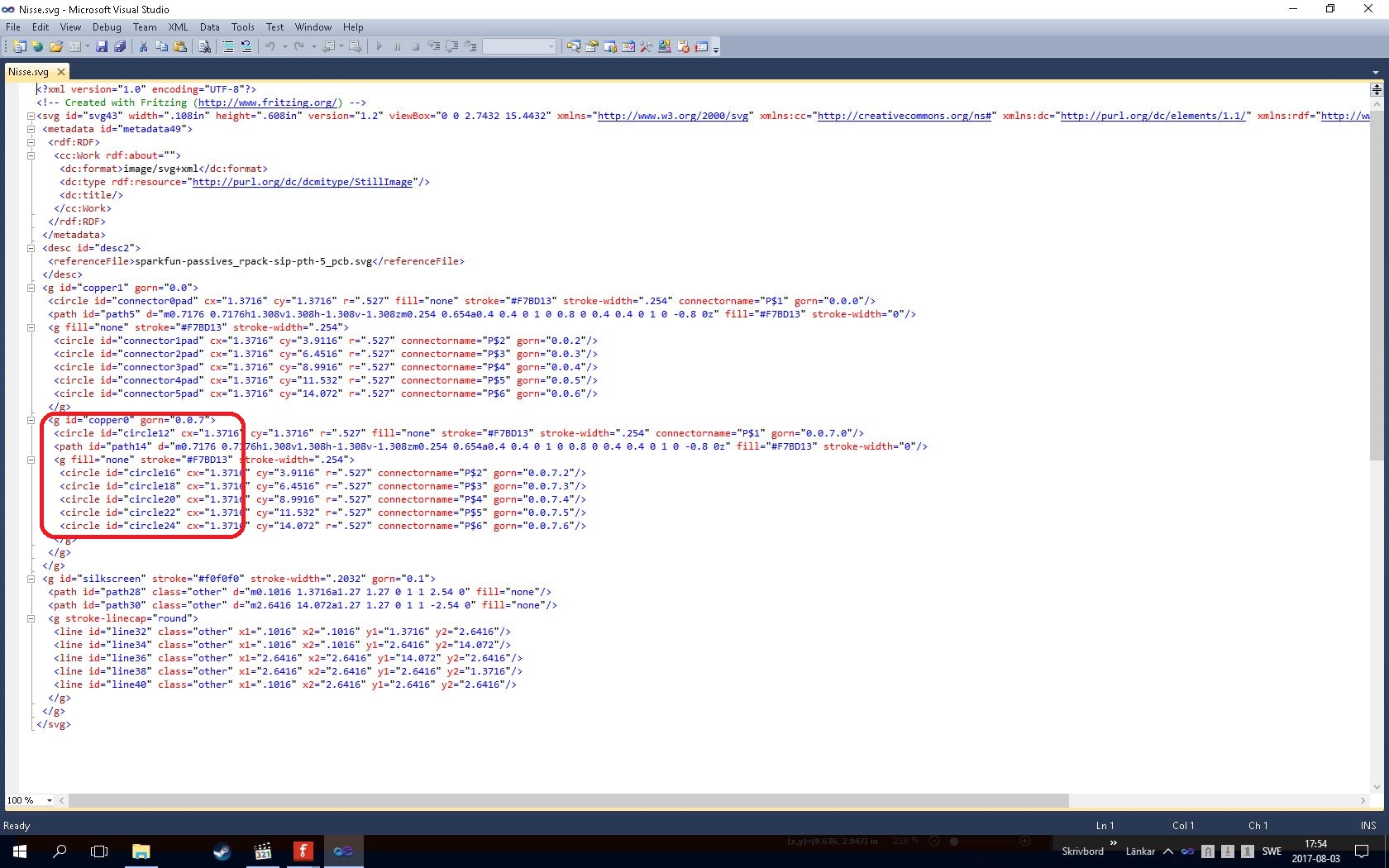
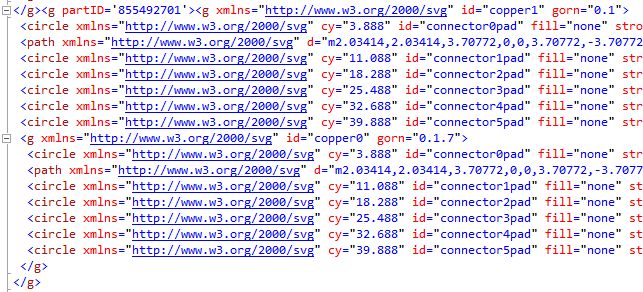
When comparing old/new file with the XML-editor in InkScape. Copper0 and Copper1 looks the same to me.
The size of the file after saving in InkScape is almost twice the original (no editing done). Is this normal ?
I used an external XML-editor to compare the SVG-files before/after saving, and the formatting looks completely different ?
Files in InkScape should be saved as plain SVG. But are there more to think about ?
(I tried uploading the two SVG-files. But it says that the size cannot be determined ?)
Looks like Inkscape has screwed up the connectors. That may be due to translates being added (check xml editor and see if the connector circles have turned in to ellipses, i.e. have both an rx and ry parameter rather than just r.) To upload the svgs change the extension from svg (which the forum often dislikes) to fzpz (which it likes) and upload them. Tell us they are really svgs and we will rename them and have a look.
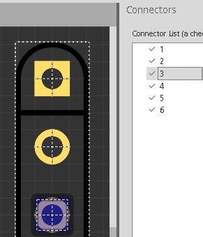
Thank you for your responce. Something is wrong with the assigning of connectors.
I have checked this again, and it looks OK to me. See images.
Grateful for more hints ?
As new user I’m only allowed to upload one file at time.
There are two ways to assign pins :-
PRE assign in Ink - I gave up on this one because I can’t get it to reliability assign in the order I want, or
POST assign in FZ Part Edit.
It’s getting clearer. Now I understand what’s wrong.
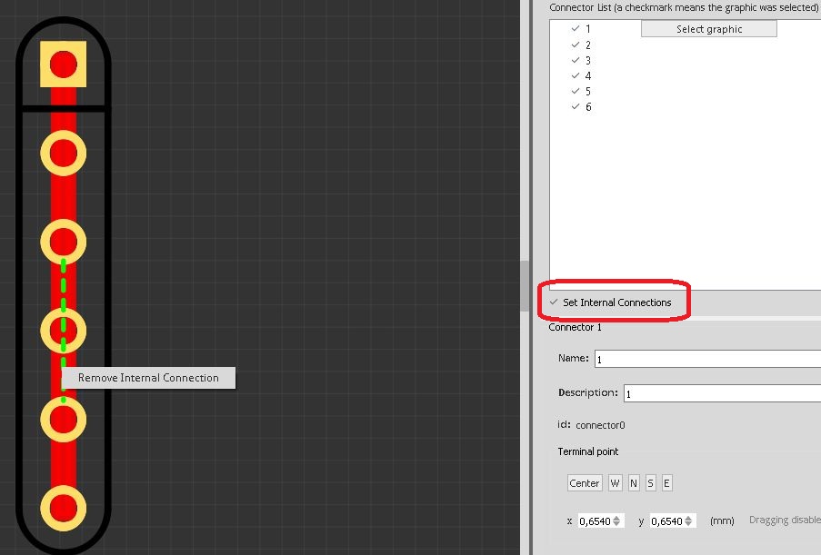
InkScape adds some kind of internal connections.
When checking the box “Set Internal Connections” in Fritzing editor, the red line is visible.
But internal connections are supposed to be green lines ?
In Fritzing Editor I can add internal lines that becomes green. And it’s possible to remove them again.
But the red line is not possible to get rid off
Although the example you started with had both Copper1 and Copper0 Fritzing no longer wants that structure. Try deleting all the paths inside copper1 only leaving copper0 inside of it with its contents intact. Then open the part in Fritzing parts editor and then use the file menu to change the svg to the new svg. After that assign the pins as needed. I do not recommend changing the file directly in the folder as it seems to cause issues like this for me.
I managed to sneak around the problem. But probably not in the best way.
In InkScape save the file in compressed SVG. This makes the fomatting more like the original, when using an XML-editor.
Look at copper0 section. Replace “circle id = circle12” with “circle id = connector0pad”
Repeat with the other pads. With appropriate padnames.
I guess the problem was what sublimeartistry described.
The original part is an old one. With both copper1 and copper0.
Today you only need to define the pads in copper0, and keep copper1 empty.
I’ve spent several hours trying to understand this problem. So thank you for your help
While I’m late to the party, I don’t see a problem in the two svg files. They appear to be basically identical in Inkscape and both should work. While the file format has changed, the old one is still supported. Could you upload the fzpz file for the working and non working svgs please? I’d like to know what the base problem here is and with all the files I should be able to tell. As well if you are trying to change the number of elements in the resistor pack someone some months ago created a python script that creates packs of any size.
[quote=“vanepp, post:15, topic:4270, full:true”]
Could you upload the fzpz file for the working and non working svgs please? I’d like to know what the base problem here is and with all the files I should be able to tell. As well if you are trying to change the number of elements in the resistor pack someone some months ago created a python script that creates packs of any size.
Peter[/quote]
OK,
Here are the fzpz-files for the two versions of the part in question. RPACK_ok.fzpz (6.2 KB)
Looks like it is a matter of the old style format. Inkscape removes the baseProfile=“tiny” and adds metadata (neither of which I would expect to do this, but it seems to ). If I take your new svg and remove the old style copper0 by deleting all the elements in copper0 then moving all the elements in copper1 under copper 0 by moving copper0 up to just under copper1 and then doing an indent node in xml editor for all the elements, the new svg works as expected. Something about the removal of the baseProfile=“tiny” and the addition of the metadata breaks the conversion in Fritzing. Here is a copy of the corrected svg (encoded as an fzpz file)
which looks to work correctly. Inkscape does a variety of things in support of CSS compliance that Fritzing doesn’t support. I’m working on a python script that will correct those I know of as well as complain about errors in the fpz and svg files but it isn’t finished yet (its at that state of %90 complete that occupies %90 of the project ). One of those is put a px on the end of font-size commands which causes Fritzing to set the font size to 0 after a parts edit (usually the second time) but there are also a couple of others. But that isn’t the problem here, that looks to be the old format svg and the change to metadata (although I still don’t see why).
But I’m still confused. Maybe at a higher level
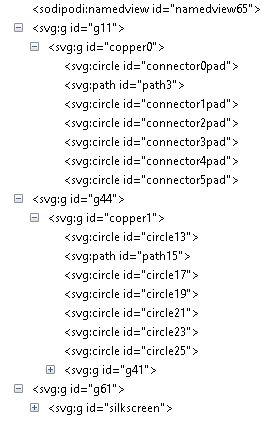
If I from the corrected file extract the SVG-file for the PCB-view, and look at it with an XML-editor. It looks OK to me. Copper0 “belongs” to Copper1.
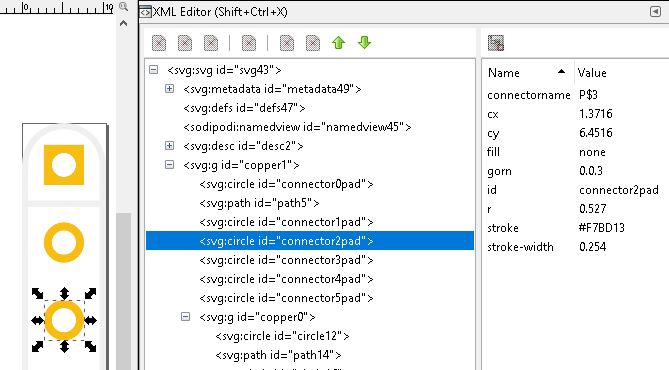
But when opening the same file with InkScape, it has separated copper0/copper1. Which is not popular with Fritzing.
I’m beginning to understand that using InkScape is not an exact science. But I think I understand now how to fix it with XML-editing.
Which Inkscape version? I did the original on Inkscape 0.91 by changing the groups with xml editor. 0.91 displays the svg correctly but I think Inkscape is up to 0.92.1 now and I haven’t yet upgraded. I’ve never seen Inkscape do something like that, did you by chance import and export it from Fritzing? The extra groups look more like the Fritzing import/export mechanism which appears to love adding groups although I’ve also not seen it add a second group like this.


