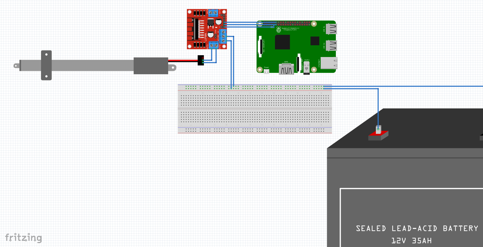
Hi, i am a student trying to create an automatic gardenhouse. We have a JS-TGZ-U3 Motor to open and close windows. We already tried to controll it but one of my teammates ruined our old controller. Now it’s my job to create a circuit that won’t blow. I am not that confident in my skills so I wanted to ask if there are any faults or issues with the circuit I created.
Thanks for any feedback to come.
Attach the .fzz sketch file (upload button ![]() is 6th button from the left)
is 6th button from the left)
Edit:
looking from your image actually the breadboard is not important, but still, attaching the sketch file is better
In addition to the sketch, the specs (including the current draw) for the motor you are using to see if the motor driver will drive it would be required.
Peter
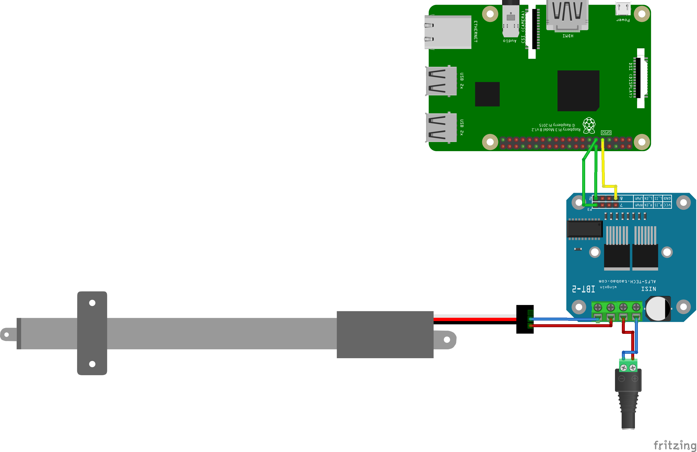
Hi thanks for the replies! I saved the file but I can’t seem to upload it, it tells me it couldn’t find my file. I also switched out the battery with an adapter because we will be using a 12V power supply.
edit.
I also switched out the H-Bridge with another one that seems to be more accessible for me
here are also the parts:
drv-1012.fzpz (14.4 KB)
linear-actuator-Actuonix-l12.fzpz (5.4 KB)
generic-ac-power-supply.fzpz (5.0 KB)
You are missing the 5V connection to the motor driver circled in red here.) I don’t know if the RPI will provide enough current on 5V to run the motor driver though so that would be something to check as well!
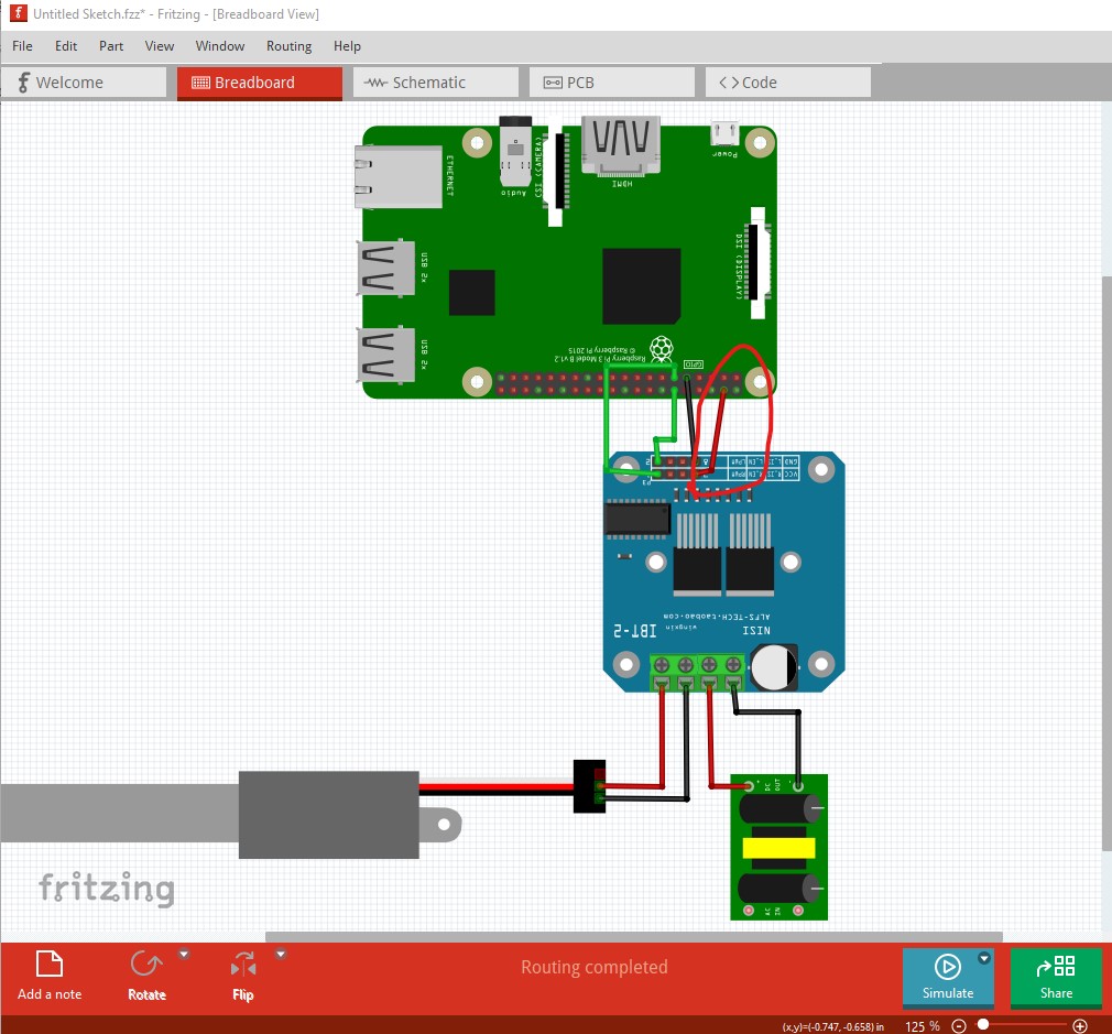
This motor driver should have enough current for most any actuator, but you need to have a 12V supply which will provide enough current to drive the actuator for it to work. For that you will need to find out how much current the actuator needs and make sure the 12V supply is large enough to provide it or this likely won’t work. The sketch is a .fzz file like this (of the sketch the image above was taken from)
Untitled-Sketch.fzz (29.4 KB)
File->Save as in Fritzing will save the sketch to a file.
Peter
Thanks for the help. What if the RasPi is already powered by an extra cabel. Like you would usually power them. I haven‘t build any of this I just wanted to make this and ask to make sure nothing blows up like last time!
You need to check on the RPI site to see how much current is available from the 5V pins. Then you need to find out how much current at 5V the motor driver takes and make sure that is less than what the RPI can provide. It may not be easy to find any of this information however … I would guess (but obviously don’t know for sure) that the motor driver doesn’t draw much current at 5V but it is safest to check before trying it.
Peter
Ok thank you very much I will just plug it in normaly, connect the cables you told me to and hope for the best. These things only cost 10€ anyways so it wont be a problem if it blows up!
I would guess that should be fine, I don’t expect the motor driver to take that much current at 5V (the motor 12V is another matter, but the external supply should be protected against over current!)
Peter
AFAIK the RPI operates at 3v3 logic level, so IDK if tye motor will have enough power (may need a DC-DC converter)
I’m just concerned about the RPI. It’s expensive, and if you supply to much power to the pins (which are not protected!) then the processor may blow and that step would be irreversible (unlike arduino which would just do a safety shutdown…)
Thanks for pointing that out. Could this be solved with a logic level converter?
edit.
I tried it like this with following part
Logic Level Converter.fzpz (9.2 KB)
i never did anything with this kind of part so I really don’t know if it’s right or not.

This doesn’t appear to be correct, the motor driver doesn’t have a 5V connection again (and thus won’t work!) and it likely doesn’t need a level converter. The RPI only provides 3.3V as a logic level out but the motor driver is likely at TTL levels (where a high is > 2.4V) and will thus work with a 3.3V logic level output without problems (if you had an input from the motor driver to the RPI, which you don’t only output from the RPI that would need a level translator but that isn’t the case here.) The logic level converter (if used) needs 3.3V from the RPI on the input from the RPI side, and 5V from the RPI on the motor driver side (with a 5V connection to the motor driver to power its logic) but as noted is likely not needed here.
Peter
Then I will remove it and try it next week. Thanks for the reply!