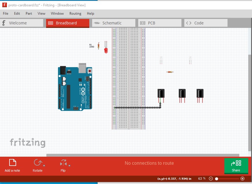
I have done my first sketch, but facing some routing issues
When in the breadboard view, it says in the lower part of the screen “8 of 10 nets routed - 8 connections still to be routed”. But when I click this message it says “There are no unrouted connections in this view”
If I click over to the Schematic view, I instead have this message in the bottom of the screen “0 of 10 nets routed - 16 connections still to be routed”
If I then go to PCB, the message says “2 of 12 nets routed - 16 connections still to be routed”
I am confused on:
Why the first view reports unrouted, but when I click it says no unrouted in this view
Why the number of unrouted differs between the different view of the same circuit
Attaching the fzz file.
I am running Fritzing 0.9.4 on Windows 10.
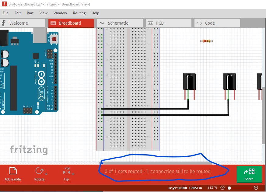
You have hit a Fritzing bug (I believe it is fixed in 0.9.5, but not in 0.9.4!) Here I deleted all the wires and just connected two grounds (which incidentally are on the incorrect pins!):
connect the second ground wire from a breadboard rail to a component not on the breadboard and we get a “connection to be routed” message even though there shouldn’t be. The solution is pretty easy, just move the parts on to the breadboard (as was originally intended anyway and easier to do in real life!):
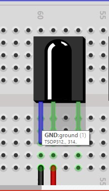
You will also see your other error here, the pins on the IR receivers are connected backwards (which would likely destroy the IR receivers if you did this in real life and powered it up!)
Here I hovered the cursor over the first pin of the IR receiver (the wire turned from black to blue to indicate which one is selected although it is obvious from the cursor position in Fritzing, the cursor doesn’t show here!) and tells me what the pin description is. In this case the pin is ground rather than the signal as in your original sketch.
Thanks! I never expect to find a bug when something I just begun using isn’t working. Always assume its something I did. This helps a lot!
As for the IR sensor, it’s actually a TSOP38238 which has OUT - GND - VCC. I should import the correct part in the the sketch instead. I assumed all IR receivers that looked the same would have the same pin out but apparently not.
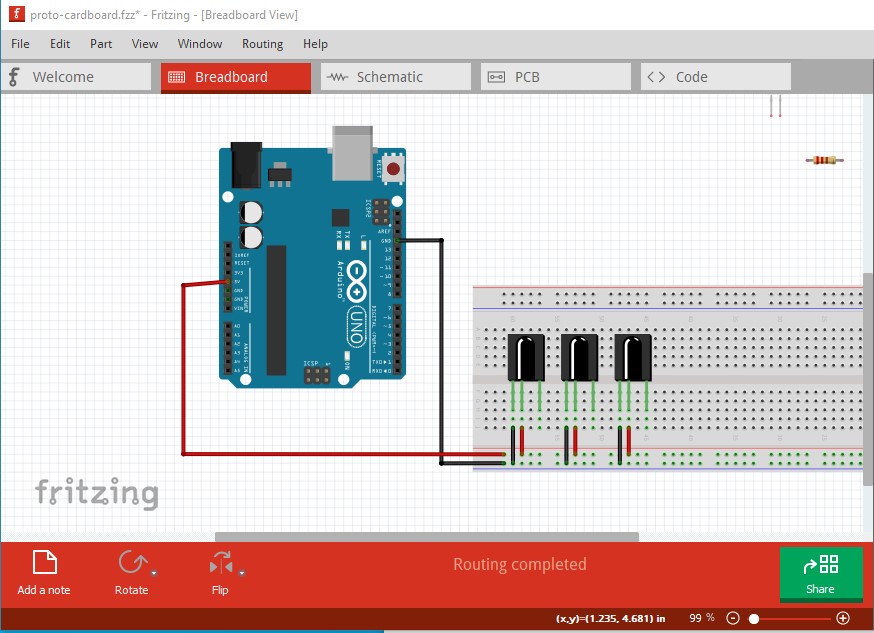
Now I have re-done it using the breadboard, and in the Breadboard view I have “Routing completed” Nice!
Buuut when I go to schematic I have “0 of 9 nets routed - 17 connections still to be routed”
And in the PCB view I have “3 of 12 nets routed - 17 connections still to be routed”
Maybe I am not understand it completely, but I thought that if all connections were connected in one view, they would also be properly connected in the other views. Then it would be more of a matter of re-arraigning the positions to get a good sketch and PCB.
Isn’t this a bit strange for the new part you made?
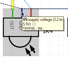
The schematic says OUT - GND - VS, but the mouse over for the middle leg says VS.
In the breadboard the mouse over is correct and says GND for the middle leg.
Not sure if this is why I can’t get all the connections okay in the schematic
More like it is a lot wrong , the original had the pins in an odd order and I forgot to change the pin numbers. I have corrected that and reloaded the part above (so you need to destroy the current version and re download the part above to get the correct version.) I have replaced it in this sketch:
To do so I selected the IR receiver parts in breadboard then right clicked and selected “delete minus” which deletes the part but leaves the wires in place in all three views. Due to a Fritzing quirk you then have to save the sketch and reload it (if you don’t, Fritzing will tell you it already has a TSOP382 part loaded even if you delete it, another bug.) Then you can load the new part and place it. After placing it (except in the breadboard) you need to click on the end each wire (which will be red for unconnected) and move it til it turns green (for connected) but with a complex part this is easier than rewiring it.
Yes the dotted (rats nest) lines reflect the connections in the other views and show the correct placement of the connections (sometimes confusingly because they take the shortest distance to the next connection!) You need to click on one and drag with the mouse to turn it in to a wire then click on the wire and move it to the correct position. It is best practice to (as you have here) complete one view (breadboard in this case) completely then use the rats nest lines to make the connections in the other 2 views. If you make incorrect changes in schematic or pcb, they will reflect back in to breadboard and sometimes (possibly due to a bug, but we have not been able to reproduce it to find out!) cause routing corruption that causes the same kind of error (unrouted nets when there aren’t any, or extra rats nest lines that shouldn’t be there.) In that case the only known cure is to delete all the traces and start the routing again. Another Fritzing quirk is that it will place components on top of each other when initially placing them so you need to drag the components in the other two views in to a suitable position to find them all. As you will see in my updated sketch (which has the new part installed) it is possible to use the ground symbol from core parts in the schematic section at the bottom to produce a ground net which makes the wiring less complex.
Ah. Learning a lot here! But I am not 100% sure about the new part. Last time you sent me a .fzpz file which I imported. But now you sent me a new sketch instead. Isn’t the part separate from the sketch? So I would need a new fzpz file?
Interesting about the ground net. Is that a PCB ground plane? Or just a way to make the Schematic view less complex?
The sketch contains the new part (because it isn’t in core parts) in the temp parts bin. However, that said I also went back and edited my original post of the part and replaced the .fzpz file there with the new version so future people downloading it will get the new part. So you can either re download the part from the post or right click on the part in the new sketch and click export part to write out the .fzpz file.
It can be (you have to set a ground plane seed in the ground network in pcb view to create it though) but it is mostly to unclutter schematic.